
M103A2 Heavy Tank
The Berlin Airlift and the beginning of the “Cold War” placed new emphasis on the US postwar tank program. The result was the emergence of three basic designs; the T41 light tank, the T42 medium tank and the T43 heavy tank With the start of the Korean War in 1950, T43 production was authorized. Continual testing and slight modifications resulted in the T43E1 which in turn became the M103. Many small defects were found but with the existence of a state of war it was felt justified to begin production of 200 heavy tanks. Most of these defects were corrected and the modified vehicles became the M103A1. The US Army placed their tanks in Europe to serve along side the M48s. However, with the rise of anti-tank guided missiles even the thick armor of the M103A1 was becoming obsolete, so in 1963 they withdrew the heavy tank force from Europe and offered these tanks to the Marine Corps. The Marine Corps accepted them only when they were modified to accept a new AVDS-1790 diesel engine, new M60 style rear hull and exhaust system. With these major changes and a score of minor changes the modified tanks became M103A2. The Marine Corps used these tanks till they were retired in 1974.
In January 2014, DML issued the M103A1 which suffered from many errors apparently from a hurried development. Late in 2014, DML released the M103A2 which while correcting some issues and making the necessary changes to convert a A1 into a A2. Some issues still remain, carried over from the initial A1 kit. With that being said, the kit does assemble into a representation of the M103A2. This will be a review of how the model goes together and areas to be aware of in putting the model together. No kit is without errors and you can build this tank OOB, but while I chose to make several modifications that in no way means you have to follow my efforts. That choice is always yours to make.
The DML M103A2 kit is typical of their products, large part count with sprues from various kits. 528 parts (185 parts not used) on 12 sprues. Six sprues labeled M48, four sprues labeled M103A1, one sprue labeled M103A2 and one sprue labeled M2/M2A1, plus 2-DS track runs (T97E2) and two clear sprues. All the sprues were flash free and very few punch out marks to speak of.
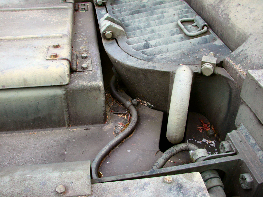
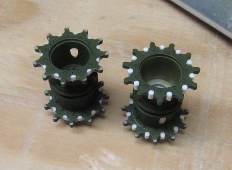
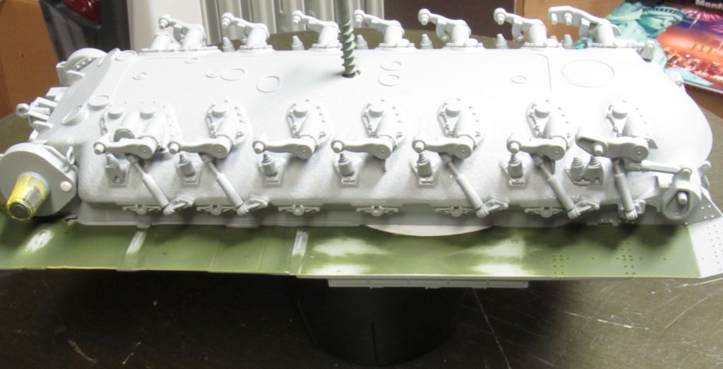
The first two steps deals with the lower hull and components. The tires (C13), wheels (C15/C17) and the return rollers (C3/C5) were painted on the sprues as I find this the easiest way to paint all these parts. Once the parts have dried I removed them from the sprues, cleaned them and then assembled them into wheels with tires and put together the return rollers. These were then set aside for later use. The two C16 parts were put together to form the drive sprocket, parts (C19/C20) which form the drive housing were also glued together. I glued this to the tank but I did not glue the drive sprocket onto the housing, saving that till after the track was on. M60s and the M103A2s all had mud holes placed in their drive sprockets to allow excess mud to get out. The kit does not have these holes. It's easy to do and only requires three oval holes on the outer section of the sprocket that are 120 degrees apart. I have attached photos of the real sprocket and the kit sprockets that I modified for your reference. When attaching the parts in Step2 I found it best to attach the tie down rings (C8/C10) first, then the rubber bumpers (C1/C2, D15/D16 and D17/D18) and lastly the torque shaft housings (C18, D41/D42 and D39/D40).
Steps 3 and 4 deal with the upper hull. For the tank I'm making parts C-9 (lifting rings) are not on the tank. Check photos of your tank if you have any to see if you need these parts on or not. You'll also need to remove two posts on the upper hull on the right side of the diver's opening. The driver's hatch rest and stop are correct for the M103A1 but not for the A-2 version. Cut these off and open up two holes that will allow you to attach the proper parts (I-7 & I-8). The final thing to do on this step is to glue the upper surface to the lower hull. Step 5 assemblies the search light. Check photos of the tank you're modeling to see whether it has a Xenon search light or not. If your tank doesn't have it, you can skip this section. If you're using the search light, note that the instructions do not mention parts J27 and J29. Go to step17 and the line drawing there gives a better idea of where these parts fit.
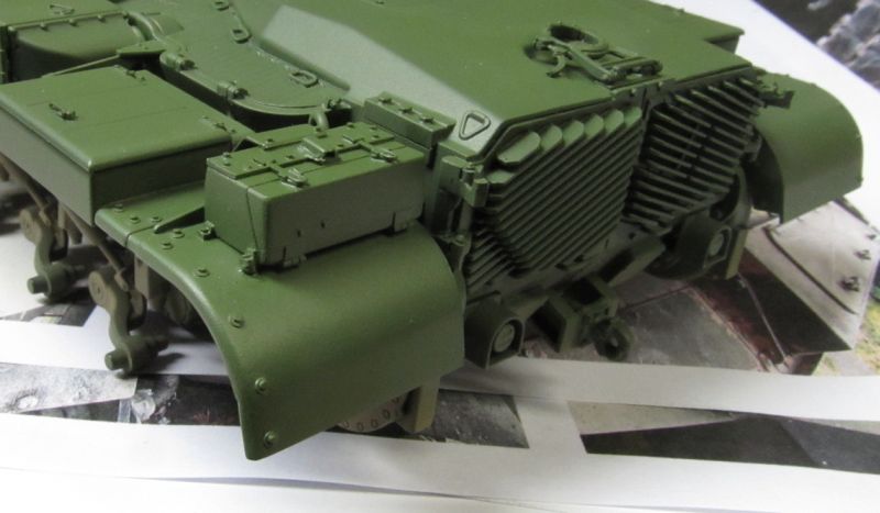
Steps6 and 7 deals with the aft upper and rear surfaces. As a guide for you: parts D1 and D4 are on the left side, while parts D2 and D3 are placed on the right. Part I-25 are the finned rear access doors. This part is correct for the M48, but needs to be modified for the M103A2. The kit part has a flat plastic piece that runs along the top to protect the fins. This needs to be removed. I used a razor saw to carefully cut the part off.
After you clean up the saw marks, you will need to remove the handles on the bottom of the doors and reposition them. Finally, add two hex bolt heads to the upper part of the doors. For reference I have attached a photo of the real tank and the modifications that I made to the kit part. You'll notice that I redid the hinges too, but while this made it more accurate I'm not saying you have to go that far. One last thing, parts D21 and D22 have punch out marks that need to be filled and sanded down. Step 8 would have you attach the road wheels, return rollers and drive sprockets, but I waited till the fenders were on a for reason that will be made clear next.
Step9 left fender assembly. Three things to note here. First, part B16 the lower part is made of rubber to act as a flexible seal, so if you have a gap not to worry, but you may also want to position it so the fit is tighter. Next, if you turn the fender over you'll notice that there is an open space, this doesn't exist on the real tank. I got some .015” plastic sheet and cut a piece out that just covered the opening. I waited till the fender was on the tank before I did this. Finally, part C6 the lifting ring is actually welded to the upper hull and the fender is cut around it. What I did was to add a piece of .030” plastic to the bottom of the lift ring to lengthen this part. I then cut an opening in the fender to allow the lift ring to clear the fender. Once the fender was glued to the hull I then attached the lift ring to the hull making sure that the ring did not touch the fender. Step10 right fender assembly, same as the left fender. Note, there is a raised outline to remove up front on the fender, a small rectangle, just scrap it off or sand it down. Once both fenders are glued on, allow overnight to get a good strong bond. I then went back to Step8 and glued on the wheels and return rollers. I still did not glue on the drive sprocket. Step11 addition of lights and other items to the upper hull. I used lead solder to make the electrical line, but you'll have to decide if you want to add the wiring or not.
Step12 gas cans. Simple step to glue four parts together for each gas can that will be mounted to the turret later. Step13 the M2 .50 cal Machine Gun assembly. Step14, 15 and 16 deals with the turret. If you want to make your model out of the box then I would keep on following the kit's instructions. It's here that I made at least five major changes and a host of minor ones, but as I have previously said you don't have to follow what I did.
Okay, let's follow Alice down the rabbit hole and see what changes we can make. The DML M2HB Machine Gun isn't bad, but I felt that Tasca's (Tas 35-L9 1/35 Browning M2 Machine Gun setB) version has better detailing so I used that. After assembling the MG as per Tasca's instructions I cut off the front sight cover and made a new cover with lead foil, bent and glued on with CA. I added a rear sight and used Tasca's charging handle, but still used DML's grip handles. I used the DML's mount, but drill out holes to put in “L” shape retaining pins and then used PE chains looped to secure the pins to the mount. The kit's ammo can (WWII design) and holder were thrown out as I scratch-built the newer .50cal ammo can and holder from .005” plastic sheet. Then used Mission Models .50cal brass rounds attached with links to sit in the ammo can. I used a mix of Tasca and scratch-built parts to make the mechanism that holds down the ammo strips as it feeds. After priming I mixed up a blend of Testor's magnesium buffing metalizer and Testor's dark green enamel paint to produce a parkerizing finish. Once this paint was sprayed on and allowed to dry the handles were painted dark brown and dry brushed with a tan color for wear. The ammo can was painted a dark Olive Drab and given a .50cal ammo decal. The .50cal ammo had the bullets painted copper and the tips were painted black and every 5thone was painted red/black. The machine gun was then set aside for later.
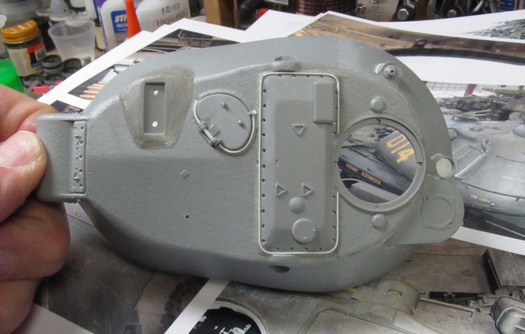
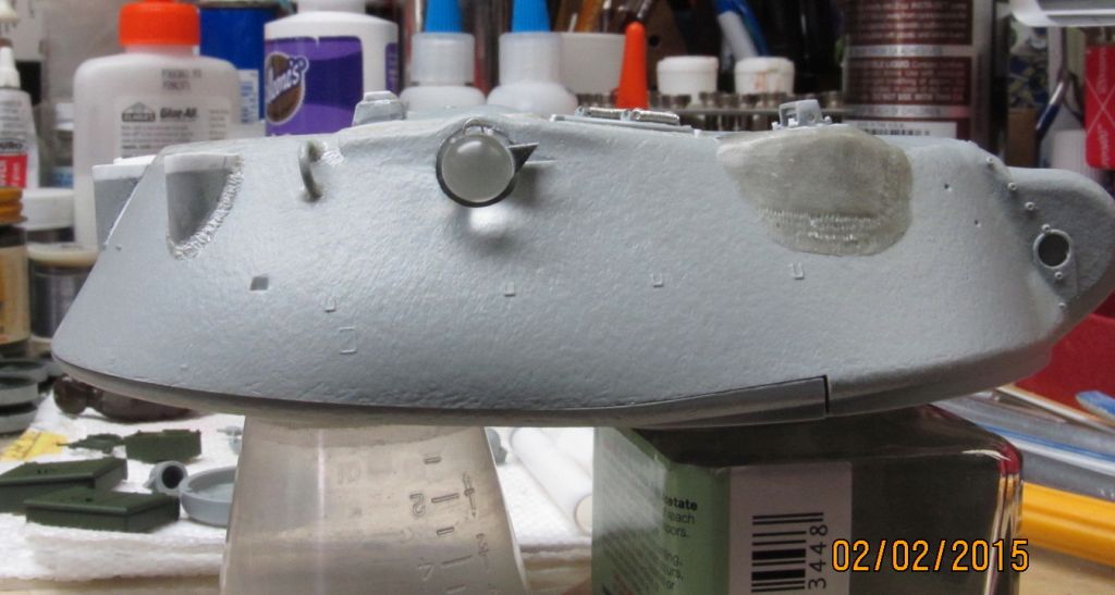
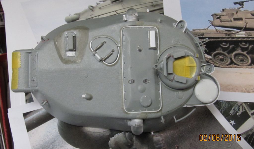
DML did correct one error on the turret from their M103A1 kit. On the turret's roof they added a peak along the center line so it slopes off to the sides. That was good, but so many other changes need to be made. If one looks at photos of real M103A2s you can see many things that are wrong with DML's range finder hatch (large hatch on the turret's top). DML made their hatch with a horizontal flat lip at the base of the sloped sides. The real A2 just had sloped side that terminate in a raised vertical lip. To make changes to these errors I needed better access to this hatch, so I used the back of a new #11 exacto blade and scribed around the hatch, going deeper and deeper until I had cut it out. I now filed the horizontal lip off and added a strip of .015”x.060” plastic around the edges to create the vertical lip, which also closed up the gap made when the hatch was cut out.
I then drilled .032” holes for the Socket Head Cap Screws (hereafter SHCS) all around the hatch. I used .025” plastic rod to make the SHCS, remembering to use a #79 drill to make the center socket hole in each SHCS. When this was done the hatch was glued in place and epoxy putty was used to make the wide weld beam around the vertical lip. That solved that problem.
Photos of the gunner's periscope housing will reveal that it was much larger than what DML has to offer. The real one is wider along the top and bulges out more on the sloped turret side with wide weld beads. This correction was made using epoxy putty. The mantlet on the kit is undersized, not wide enough. I added some .100” balsa wood to the sides of the mantlet (F38) and then filled in using epoxy putty. The same method was used to widen the area on the turret that takes the mantlet. Only here I had to drill holes in the sides and then later add a plastic strip to duplicate the area that was there before.
Up till now things have either been too small or not wide enough, now with the bustle rack it's a case of being too tall and the spacing of the center rail not being in the right place. I'm trying to match the photos, so I start by using a razor saw and cut out one of the center horizontal rail. This was repositioned .062” further up and then glued in place. Then using a pair of plastic snipes shorten one of the vertical rails by .100”. I let this dry well before the next cut, by repeating this process I was able to reposition the inner horizontal rail while at the same time reducing the height of the rack.
Both the long and short racks (F22) had this done to them. Then all the racks and hand rails had holes drilled at he ends to simulate tubing. The two racks were attached, but not where instructions indicate as this was too low on the turret. I had to position the racks at least .125” higher to make room for the towing cable.
Another modification that came about by looking at photos was part F1 – Ventilator blower cover. The kit's is undersized. I punched out a 5/8” disc from .060” plastic and rounded the edges and smooth out all file marks. I then drilled four holes at the edge and glued in a piece of .060” plastic rod that I had already drilled out a .032” hole. Once glued in place, a piece of .025” plastic rod was glued inside the small hole to create a SHCS. Before this was mounted I removed the thick lip around the blower cover stand-off and the antenna stand-offs. I used glue to attach strips of .100”x,015” plastic to remake the lips thinner.
At the turret rear there is a drip edge that makes condensation or rain fall off the turret onto the upper deck to prevent it from rolling down the turret undersides to the turret ring. The kit's drip edge isn't distinct so I sanded it off and glued down a piece of .025” plastic rod. Then using some .010” rod I created a weld bean on both sides of the drip edge. I also redid the DML tow loop clamps as they are simply a block and wasn't anything like the photos of the real ones. Taking a piece of .040” plastic I drilled a .040” hole then cut the plastic thru the hole to make two blocks. Glued the blocks to the turret sides and then glued the tow loops (B13/B14) onto them. I cut a strip of lead foil and bent it so it would go over and create a clamp. On one end I glued a piece of plastic rod to make a hinge and on the other end I glued on a wingnut to hold the clamp shut. I used strips of lead foil to act as retaining clamps to hold the tow cable in place.
Photos of the turret's back shows several tie downs are located to be used to secure items to the bustle rack. I made these using .020” copper beading wire, using a smooth jaw needle nose pliers I first cut a piece about 3/16” long and using the pliers flatten the first .040” on each end. Then using these pliers I held the center section and bent the ends down and using another pair of pliers I bent part of the down pieces back up. Takes longer to write then it does to actually make the five tie downs that I needed. These tie downs were glued to the turret using CA, with photos used to locate where they went. Another small thing to do is to drill a .020” hole into the antenna stand-offs to allow water to drain from the base of the antenna.
On either side of the commander's cupola are two small domes. These were on the A1s but were not on the A2s. The real ones were either ground down or cut off with a cutting torch. In the model case I used a dremel too
to grind the dome down, but still leaving a little at the base just like the real thing. On the range finder's hatch at one corner sits a rectangular block. Photos show that another smaller rectangular block sit on top of this. I used some .030” plastic sheet to recreate this feature. Also on this hatch are three lift rings that are triangular in shape. I wasn't liking the kit's version, so I decided to make my own. I first took a piece of .040” plastic to use as a base. I then used some .020” plastic to make a triangular pattern that would fit inside of the lift rings. I glued this pattern onto the base and let it dry overnight. The next day I used some .010” wire and bent it around the corners to make the lift rings. A small strip of lead foil acted as a hinge and then I removed the plastic lift rings from the hatch and attached the new ones I had made.
After looking at several different A2s I came to the realization that the M24 range finder end housing (F8/F9) that DML provides is undersized. Not by much, but enough that I wanted to remake them. I have some acrylic spheres that I have gotten from various Craft stores and on this occasion I used two 5/16” spheres. I glued these to the ends of two 5/16” plastic tubing. After curing overnight I chucked one into a lathe and turned the sphere down till it blended into the shaft. Repeating this process I had the makings for two end housings. Using a Dremel tool I was able to enlarge the existing hole not only to fit the new range finder end housings but also to fit the flange that allows these housing to be bolted to the turrets side. I glued one housing into this opening and after checking the alignment I let it dry overnight. The next day any openings that hadn't been covered by the housing/flange was filled with some epoxy putty. The flanges themselves were made from the next size in the plastic tubing range, using a lathe to make the cuts. The flange was then glued to the housing before it was glued to the turret. Also before I glued the housing in place I had to use the Dremel tool to route out an shallow opening where the range finder lens would be placed. Later after both housings were solidly in place I came back and attached hex bolt heads onto the flanges that are visible when the housings are viewed end on. I then used lead foil bent into shape that was then CA onto the housing to protect the lens from dust and sun. Finally, I had to drill two holes onto the top of each housing to accept a lift ring that was made from wire bent into a “U” using CA to glue it in place.
Working our way down to the front of the turret the gunner and loader's hatch had the molded on springs removed. Two new springs were made from
.010” wire wrapped around a rod and then glued to the hatch. The hinges were modified form what DML provided to more resemble the ones on the real tank. Using some .040”x.010” plastic strip I bent it around the gunner/loader's hatch where it was missing on the kit's hatch. I then used some epoxy putty to recreate the weld bead around the new lip and blend it into the kit's weld bead. Finally, I made a latch for the hatch from bits and pieces of plastic. Part F43 is the electrical connector for the Xenon searchlight.
First off, if you followed the kit's instructions you would fill this hole, but don't do that. Whether the searchlight was mounted or not this connector was always on the A2 tank. I cut the connector off the kit's housing and replaced it with a slightly larger and longer piece of tubing. I also scratch-built the connector cap and used a fine wire that was glued to the cap and then onto the housing, so the cap would not be lost.
A little while back I used some epoxy putty to enlarge the gunner's periscope housing. I now needed to replace the kit's part F19 as it was now not thick enough. The periscope base was remade using a thicker piece of sheet plastic. Then holes were drilled into it to accept rods which would become, you guessed it, SHCS. Seems like all the screws on the turret roof were SHCS. Moving along here so fast I forgot to mention the commander's hatch. I wanted mine open, but DML really doesn't give much details for this, so I added a piece of .020” plastic to the bottom of the hatch to create an inner lip. I then made a small ball of epoxy putty and placed it on the bottom and pressed down on it to flatten it and make a head cushion. I used a piece of clear sprue filed down into the shape of the lower part of the periscope. Hold downs and wingnuts were added to finish off the look.
Finally, using some of that copper beading wire I bent a handle and glued it to the top of the hatch. The hatch was then glued in the open position.
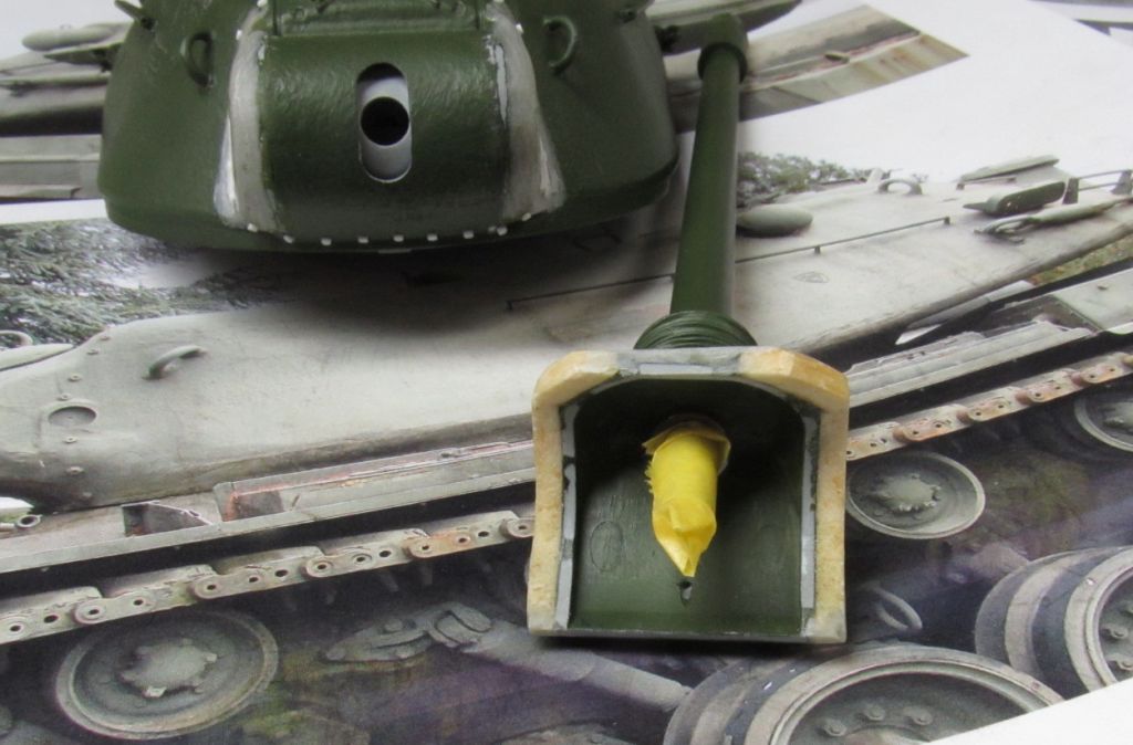
One of the biggest shortcomings of the kit is the barrel which is short by about 16mm or close to 3/4”. You can try to live with it, but why bother when you can buy a replacement barrel that is made from turned aluminum/brass. I chose to buy the RB Models#35B132 barrel and had no problems in using it. Voyager also makes a replacement M103A2 barrel if you prefer them. One note on the RB barrel, the most forward brass piece (the counterbalance) has a notch, this notch must face downward and needs a hex bolt head glued in it as it was there to hold the counterbalance and the evacuator chamber onto the barrel. It's not part of some barrel sighting system, so please don't put it face up or try to putty it up. See Hunnicutt's book FIREPOWER, page 137.
As I mentioned earlier I widen the mantlet (F38) so do not add the lifting rings (F17) till after you have widen it, if you so desire. If you do decide to widen it, you'll need to cut off the two tubes on the mantlet. These tubes need to be moved further out to match the amount the mantlet was widen, don't changed the tubes position vertically. Now the lift rings can be added right above the tubes. So you're moving the tubes/lift rings the same distance right and left and their position to one another doesn't change vertically.
Before the mantlet cover is made I needed to add the bellow-like arrangement at the rear of the barrel. I punched out about 10-12 1/2” discs from .010” plastic. One then has to make a center hole, since these discs fit over the rear of the barrel where a taper exists. The largest hole will be on the first disc and the smallest will be the last. I have attached a photo that will show you what I'm talking about. I used CA to glue the first disc on and then using some .020” square stock I cut a bunch of short pieces and glued four around that disc. This will space the next disc .020” from each other. Keep repeating until all the bellows are in place. I use epoxy putty to fill the area between each disc. After this had cured I glued the barrel/mantlet onto the turret. After this I began to cover the mantlet with tissue soaked in a water/white glue mix. I laid up several layers and worked the material to create wrinkles. I use photos of real mantlet covers to get an idea of the types of wrinkles one would see on the real tanks.
These extra detailing steps were not only confined to the turret, I did some on the hull as well. I've already mentioned the work on the engine access doors at the rear. Well the rear fenders were extended down by 3/16” using strips of plastic sheet. Washers and nuts were also added, top and bottom, in this area and a new infantry phone box was scratch-built as the kit's was too small. You'll also may want to add the cable that runs from the rear of the phone box thru the fender bracket and into the hull. I used a length of .032” lead solder for my cable and before the fender went on I had predrilled a hole in the hull where the cable would go into.
There are numerous areas on both fenders where I added nuts and bolt heads to match photos and were lacking on the kit. When I added these on the fender tops I made sure I matched them on the fender bottom with the corresponding nut, The latch handles on the various fender boxes were modified as the kit's ones were solid and didn't look right. I cut the handles off and used some .010” plastic square stock to make new latch handles I also added new triangular lift eyes to the side loading air filters using the same fixture and method that I had used on the turret.
DML provides two DS track runs for their model. I've used DS tracks before and have had no problems, but for some reason the tracks I had in this kit, had a lot of flash on the end connectors and around the teeth that's impossible to remove. I was left to buy some new workable tracks made by AFV Club (AF35005, T97E2 tracks). It took about two days to clean them up, but they assembled real easily. The real M103A2 used 81 track links per side and the AFV Club track links came to 81 per side as well. I started the run at the front, pulling the track over the return rollers and then added the drive sprocket and pulled the track over and around that, then used two end connectors to complete the track run. Of course, the model and the tracks were painted by this time. Check your DS track runs and if don't have any flash, then there is no reason to go out and buy new tracks.
Painting – Before painting I used Archer surface detail resin casting marks (AR88007) to apply casting number on various locations on the turret. These are on clear decal film and can be applied like decals, making application easy. Prior to painting I also made sure that I taped up all the periscope openings with tape. I used a rattle can of Krylon satin black primer to prime both the hull and turret. The kit instructions would have you paint the model in Olive Drab, but all the M103A2s were used by the Marine Corps and should me painted in Marine Green. Now with all the paints that I have I didn't have that color, but I decided to use what I believe is a close match -
Mr. Color No.136, Russian Green #2. So I mixed this with some Mr. Color Self Leveling Thinner and used by spray gun to paint the hull and turret. After drying overnight I mixed a lighter shade by using Mr.Color No.136 but adding Mr. Color No.60, RML02. This lighter shade was sprayed onto the upper surface of both the hull and turret, with a lesser amount on the turret sides. Again after this paint coat had dried I dry brushed some of the raise details using some straight Mr. Color No.60, RML02
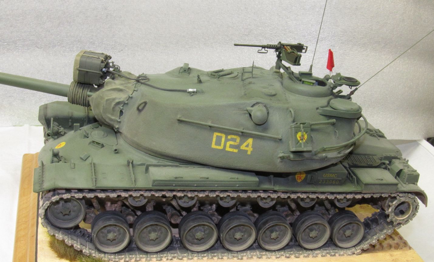
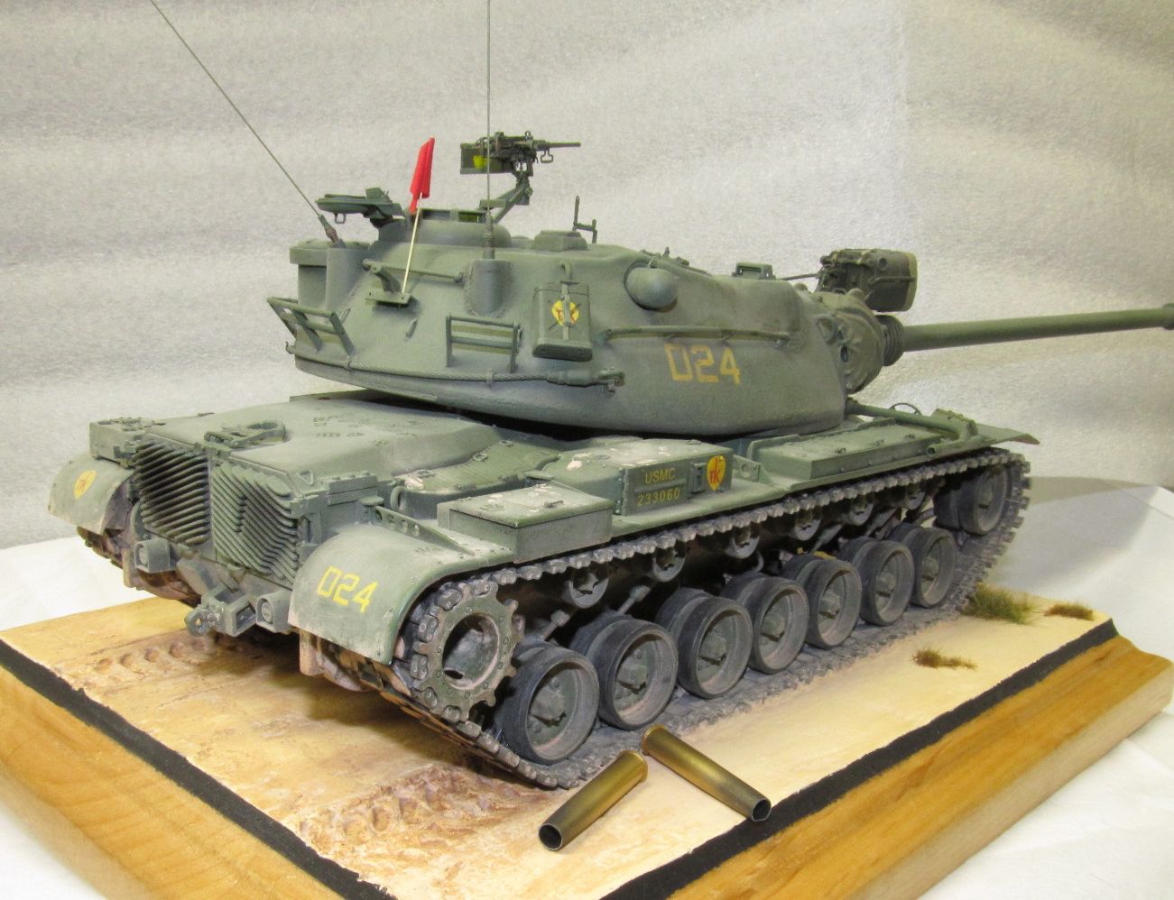
Decals – The vehicle that I'm building can be found on page 150 in R.P. Hunnicutt's book FIREPOWER. The vehicle is a M103A2 from the 2nd Platoon, D Company, 5th Marine Tank Battalion operating at Camp Pendleton in June, 1967. I'm not making an exact copy of this vehicle, but the model is based on this vehicle within that time period. DML provides decals for two vehicles both with unidentified units at Guantanamo in 1970. I can't verify if the DML decal's font and size is correct for 1970, but I know from photos that the letters are too thick for the 1967 period my tank will represent. I was able to find some yellow letter decals that would work and applied them. I also needed a smaller yellow size for the right rear fender. Again I was able to find them within my decal stash. I was able to use DML decals that had the USMC and serial number, these were placed on the air filters. I had no problems in applying these decals. DML also provided shield decals (3 of them), but I needed six, so I had to used a solid yellow decal to make the body of the shield and smaller red letters to fit inside the shield area. After the decals there applied and had dried, I gave each a coat of Future to seal them.
Weathering – I started by applying A.MIG-1005 Dark Brown wash for Green Vehicles on the upper surfaces of the hull and turret. I wiped off the excess and allowed that to dry. Before I did any more weathering I wanted to make the base and mount the tank on it. I used an old plaque as the base and spread some spackle on the top. When the surface was dry to the touch, but while it was still soft I did use the DS tracks by pressing them into the surface to leave the track imprint. The spackle easily washed off with some warm water. When the spackle had dried I used various Acrylic paints to create the base color. When I had mounted the tank to the base I could then begin my weathering. Photos show the lower hull slightly muddy with a coating of dust over the vehicle. I mixed several MIG pigments together to match the base color. Mixing some of this pigment with lacquer thinner I then spread it over the lower hull, under the fenders and all around. When that had dried I used some clear flat lacquer to darken some areas as if the mud was still wet but drying. I also made a thin mix and flicked the bristles of a brush to make mud splatter on the lower part of the vehicle. After this I just used the pigment mix to dust up the upper hull and turret. To create the exhaust stains on the rear engine access doors I used black MIG pigments.
The Hunnicutt book shows at times many people on the vehicles, generally on the fenders. So using some old Caliber 35 flexible boots I able to make boot prints and scuff marks along the right fender, on top of the engine and on the top of the turret. I also mixed up some pigment thinned with thinner and made a few muddy boot prints starting over the right drive sprocket and slowing getting lighter as they went forward along the right fender. This tank was on the firing line and as result carried a red flag to denote live ammo being carried. I cut a piece of tissue to a small flag size and painted it with red acrylic paint, when it was dry I soaked it with water and white glue mix and attached it to a prepainted plastic rod that represented a dowel. I let it drape down as if no wind was blowing. I attached the Machine Gun to its mount and added the antennas to their bases. Finally, since the vehicle was on the firing line I wanted to make two empty cases that had been ejected after firing. Hunnicutt's book lists the length of several different rounds, I went with one whose length was for the AP round. The dimension was in inches and if you divide that by 35 (since the scale is 1/35) you come out with the scale length in inches. In this case just under 1 inch. The round is 120mm in diameter, now if you multiply 120mm by .03937 that will convert the mm into inches, then divide that by 35 results in a dimension of .135 inches. I have some plastic tubing so I used the one whose inside diameter was .125” and used a #29 drill (.136” size) to drill out one end. I put it into my lathe and made a taper from midpoint to the enlarged end. Cut the piece to length on the lathe and repeat this for the second casing as well. Finally, I punched out 3/16” discs from .010” plastic and glue them on to make a rim, drilling out the discs for a primer strike. I painted the cases with Mr. Color Brass and used MIG black pigment to create the discoloration caused by firing. These were glued to the base and the model was done.
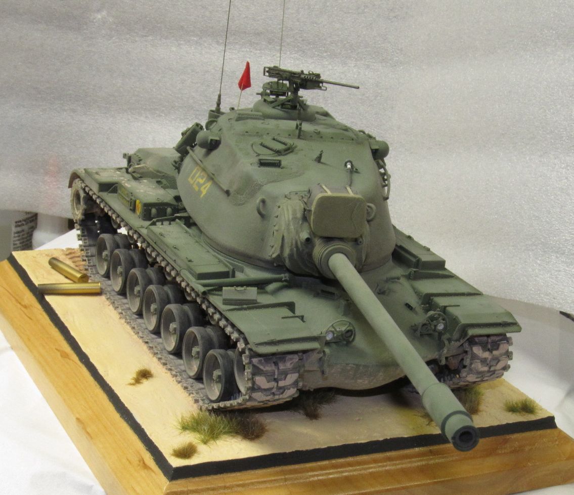
I can recommend this model to anyone who wants a modern heavy tank that the Marine Corps used. I would suggest that at the minimum one needs to buy a replacement barrel and make a mantlet cover. Those two things would go a long way to improve the tank's look. While I did many extra things, you do not have to, have fun and enjoy your build.
I want to thank IPMS and Dragon Models USA for the opportunity to review this model.
References
- FIREPOWER: A History of the American Heavy Tank by R.P.Hunnicutt published by Presidio Press, copyright 1988, 224 pages
- M103 HEAVY TANK 1950-74 by Kenneth W. Estes Illustrated by Richard Chasemore, New Vanguard #197 published by Osprey Publishing, copyright 2013, 48 pages
- WEB PAGES – Walk around photos
- Prime Portal M103A2 5 pages tank located at Ft. Lewis museum, WA
- Toadman's Tank Pictures M103A2 at Military Vehicle Technology Foundation, CA


Fume vent
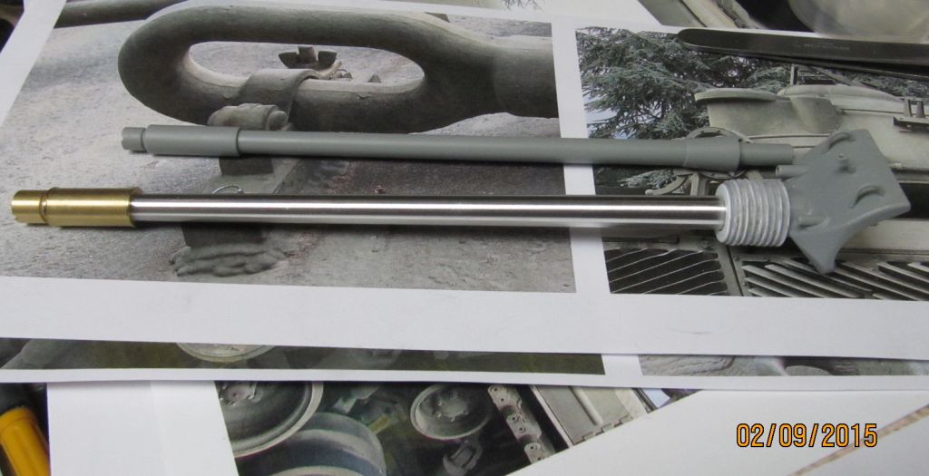
barrel comparison

Search light
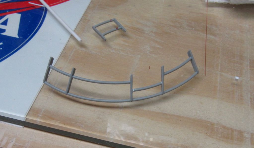
Rack
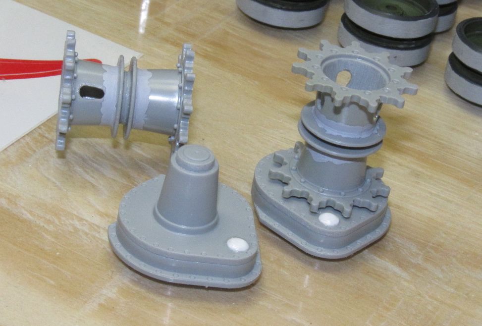
Drive wheels
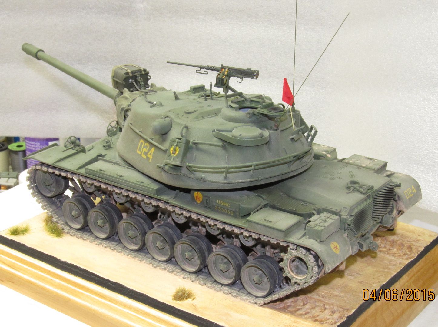
Finished model
Fender cutout
Mantlet widen
Drive wheel

Rear fenders
Front view
Left view
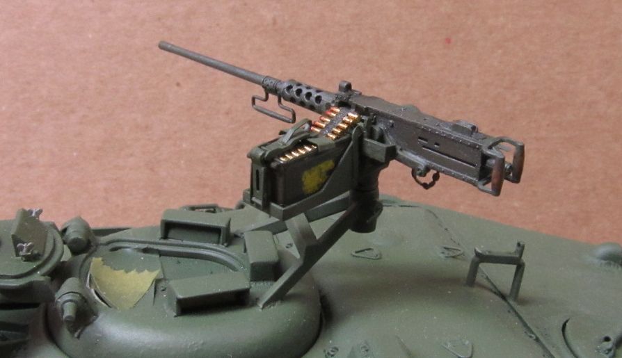
MG
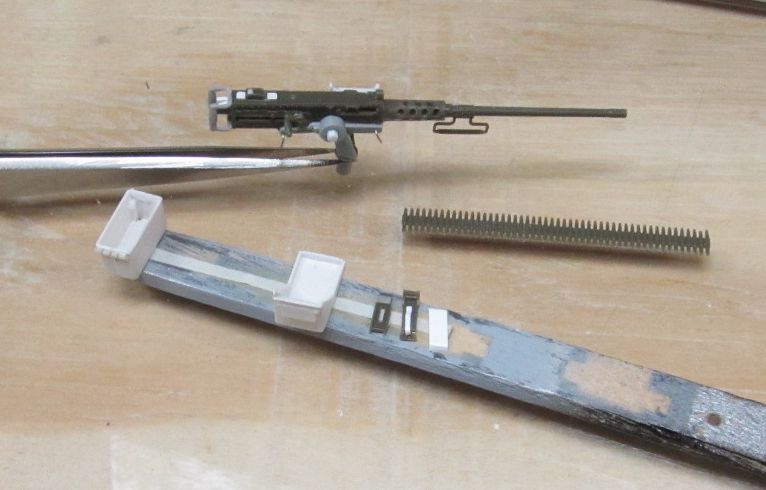
Ammo cans

Infantry phone box
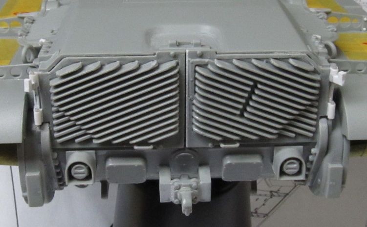
Exhaust doors
Fender extensions
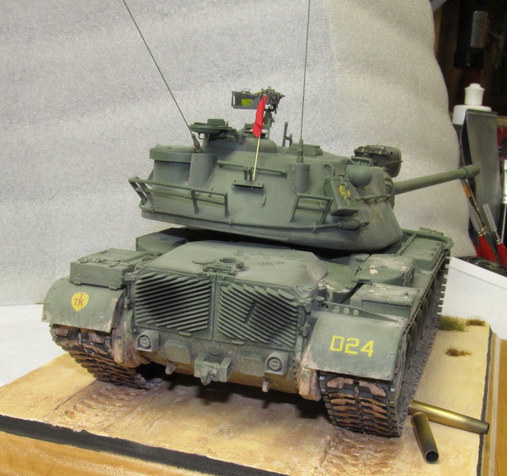
Rear view

Right view
Turret cutout
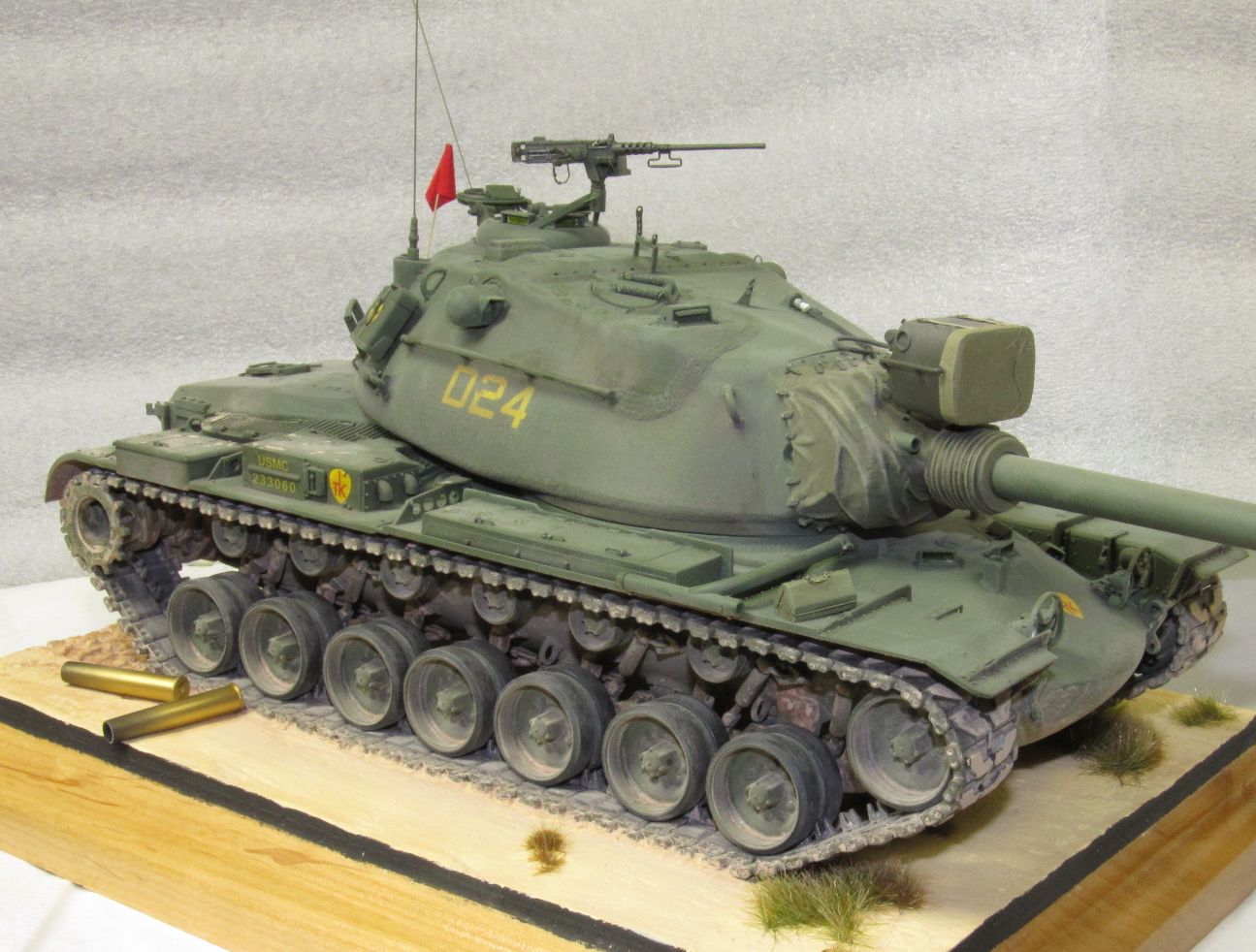
Right view
3/4 views
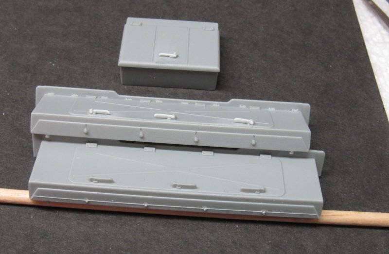
Tool boxes
Top view turret
Fenders

Turret

Barrel
Rangefinder

Lifting rings

Range finder

Turret changes
Comments
Add new comment
This site is protected by reCAPTCHA and the Google Privacy Policy and Terms of Service apply.
Similar Reviews