
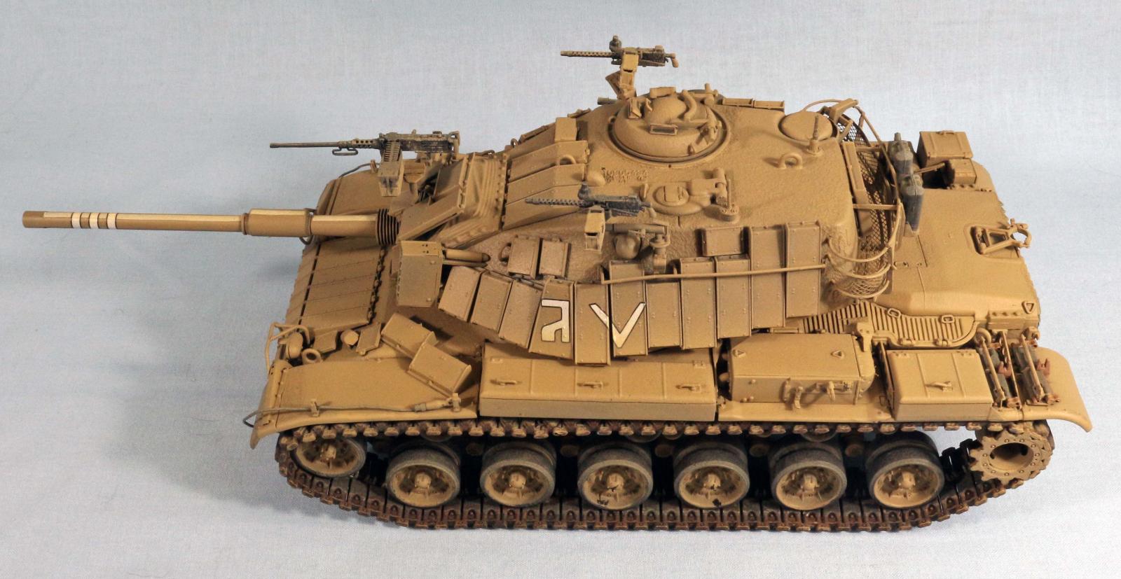
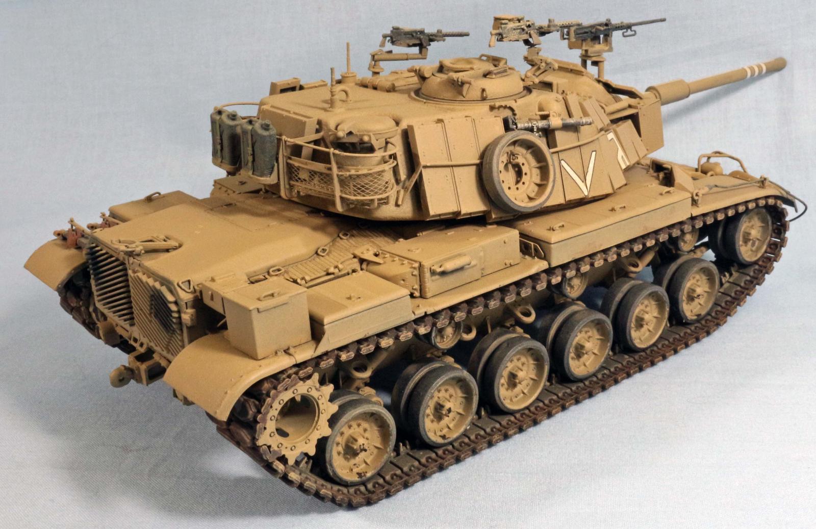
IDF M60A1 Magach 6b
Intro
The IDF M60A1 Magach6b by AFV Club is another one of their M60 series of vehicles including the M60A1, M60A3, M60A2Early& Late version and the M728 CEV as well as several foreign subjects based on the M60 series of tanks. The M60A1 Magach 6b is the version of the Magach 6 that was upgraded with Explosive Reactive Armor tiles. This kit includes sprues from the common components of the hull and turret and running gear. The Magach 6b specific components are included to model the vehicle.
Background
In 1971, the IDF (Israeli Defense Force), procured 150 M60A1 Tanks from the United States in part to replace the slower British Centurions. They named them Magach 6 and the M48A5’s (Magach5) were deployed to the open terrain of the Sinai Peninsula. This Armor was in operation during the 1973 Yom Kippur war and suffered high casualties due to the Egyptian deployment of wire guided anti-tank missiles and RPG 7’s. The IDF continued to procure after the Yom Kippur war to replace M48’s and M60’s that were lost due to battle casualties and attrition. By the late 70’s The Rafael Company developed Explosive Reactive Armor tiles that could be fitted to the exterior of armored vehicles to prevent losses to anti-tank missiles and rocket propelled grenades. In 1980 the IDF upgraded the Magach 6 with an upgraded Continental AVDS 1970-2C Diesel engine and other components including ERA tiles and re-designated it the Magach 6B. In 1982, the Magach 6b saw battle in Lebanon. The US Marine Corps upgraded 170 of its M60A1 tanks with the IDF ERA tiles used on the Magach 6B, along with other modifications.
Opening the Box
There were approximately 15 sprues molded in clear, black and olive green plus the metal barrel decals, vinyl components and tracks. Parts count is over 500
The Instructions
The instructions are a 20 page booklet with a color slick front page and the color slick 4 view schema rear page for the four decal options. There is a Sprue Tree map on page 19 and a notes and colors chart on page 2. There are 36 assembly steps. Discrepancies will be noted in the build notes. There is a separate color box art flyer.
Things to consider before building:
- You will have more parts than required to build the model since many common M60 parts aren’t always used.
- The vinyl components(Main gun and commander machine gun shroud) can be glued with liquid cement, but be careful it will eat the plastic, work slowly and clamp or hold until parts are adhered, or use alternate cements
- Almost all the photo etch is used for the bustle rack bottoms and sides, you will mostly use these for strength during assembly since the tubing is styrene and delicate and difficult to arrange with the bracing. This will be the most difficult part of the assembly process.
The Build
Lower Hull and Suspension
- Steps 1-6 covers everything track and suspension related. It’s very straight forward. Other bits included are the lighting and tow pintle, lifting eyes and bump stops.
- The shocks/snubbers and mounts(C9,D9,C17) need to be snapped together into upper, snubber lower mount first since it will be near impossible to do if you try to snap the snubber into the mounts after you glue them onto the hull and road wheel arm. There are three assemblies each side, two front and one rear, with different part numbers. Use above as model for the other stations
- The most forward snubber is mounted to the road wheel arm ,C80, and a link forward of the snubber mount goes to the idler ,D18,so this road wheel arm has an additional link C51, that goes to the front idler, D18, and is secured with C38. You may have to fit the snubber first before the idler link so it is stable enough to glue C51, it’s one of those 5 hands steps.
- The road wheel arm has the torsion bar, which is keyed, molded on it, it will fit inside the mount holes, but the fit is tight thru the hull. You may want to fit sand it so you don’t break it while inserting it across the hull, Use caution.
- The road wheels have an O-ring sealed between them to retain on the road wheel axle. You might want to wait until after painting, as the underside of the tank is pretty busy and the road wheels block painting a lot of that.
Upper Hull and Decks
- Step 7 is the driver’s compartment. If you want that level of detail it is spread across the bottom hull, inside of the forward hull. It is very detailed and the parts are delicate and fragile, I kept breaking thin parts, so I closed it up and moved on.
- The drivers hatch (step 8) is attached to a torsion bar that is glued onto the bottom side of the top deck, it might be able to be just glued into the hole. The drivers vision blocks are pushed up from the inside of the deck, do this before you attach the front deck onto the hull. If you bypass the driver’s compartment, this is easy to forget.
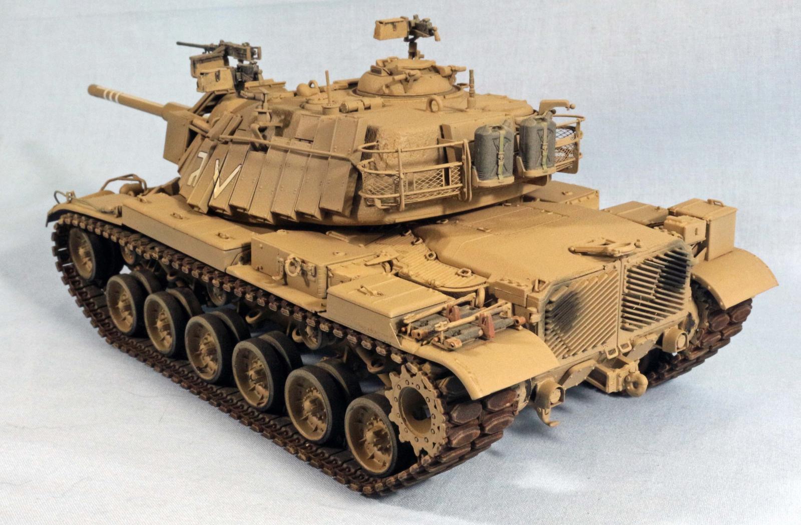
- In step 10 There are the grill door hinges that are on the outside of the hull at the rear (D22Rt Side D23 Lf Side) these are easy to miss so glue the grill doors on first then glue the back deck on to align everything.
- The grill doors, C87, 88 in Step 10 can be fitted with the back deck, K47. Use C90 and fill the hole on the right rear grill door, this is not listed or shown, but it will be obvious when you look at the part as the grille, is uneven without it.
- There are 10 top deck access doors that cover the gap between the hull and the back deck. There are triangular and “D” handles that go on the access grill covers, you just glued on. They are small and delicate and easily broken if you don’t use a sharp cutter like a God Hand to trim them from the sprues. Tweezers will fling them everywhere if not careful as well. They really add the detail however so the attention will be rewarded.
- You may have to make a decision on when to put the track on. The instructions show them being applied before the fenders get glued on, you could leave them off if you are careful threading them over the sprockets and connecting them underneath. When in place, they obstruct airbrushing all the bits under the hull between the road wheels and fenders, Builder choice on when to thread the track. The under fender clearance is tight, but workable.
The Track
Not much here, the two tracks are some sort of synthetic rubber but it is connected by a pin so you don’t need to glue it or staple it. The section that is pinned can be torn so be careful
The Fenders
The fenders and associated hardware are covered by steps 13-19. There are extensive brackets that reinforce the attachment of the fenders themselves as there is a single side with a thin cement line to hold it. Pre-assemble the fender boxes and the air cleaners before mounting them, the box latches are small and can be lost (C81). In step 18 you have to assemble the spare track blocks which have mounting brackets that are delicate, use caution.
Hull Armor Tiles
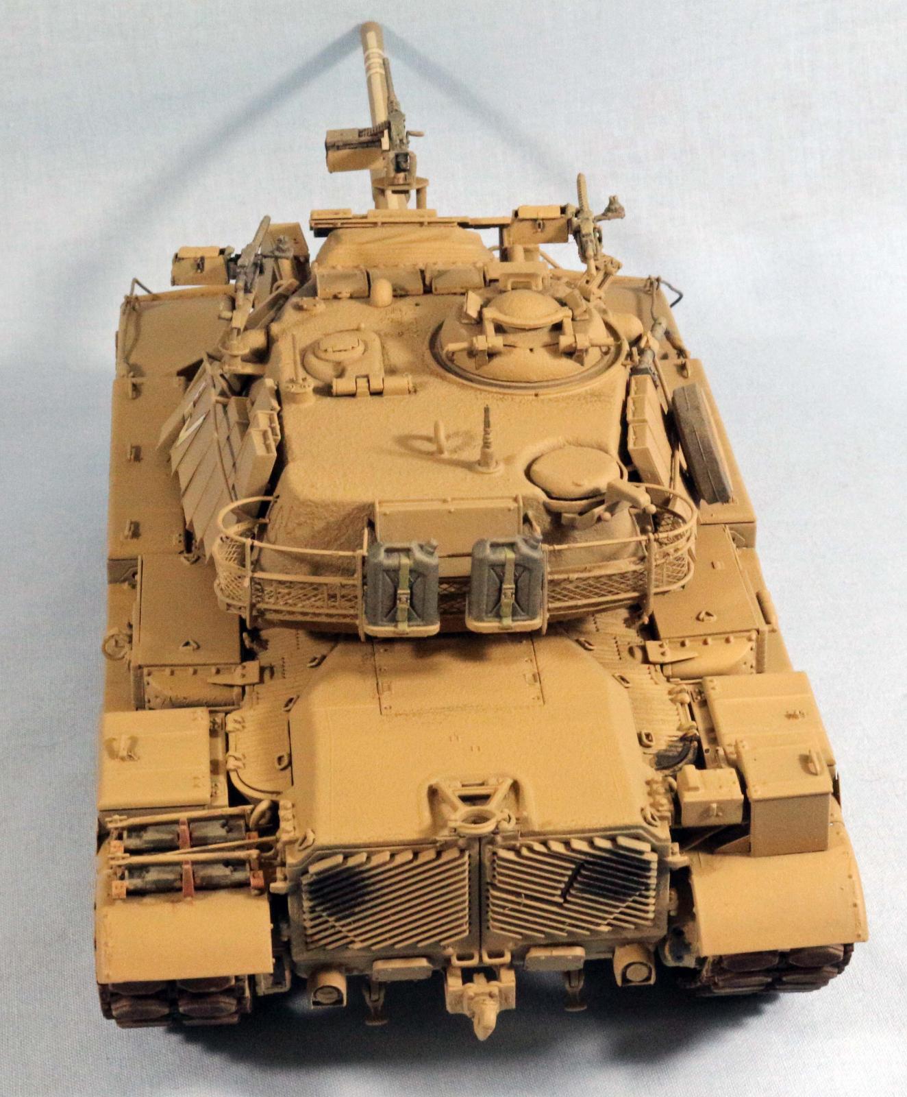
Step 20 shows the upper and lower front hull armor tiles being attached. The lower (W10) and upper (W9) are one piece with multiple tiles molded so this is easy to locate as there are marks, however faint. To position it look at the overhead view. There are multiple individual tiles to locate as well shown in the overhead view. The headlights and headlight guards as well as couple of fender supports are also fitted in this step.
The Turret
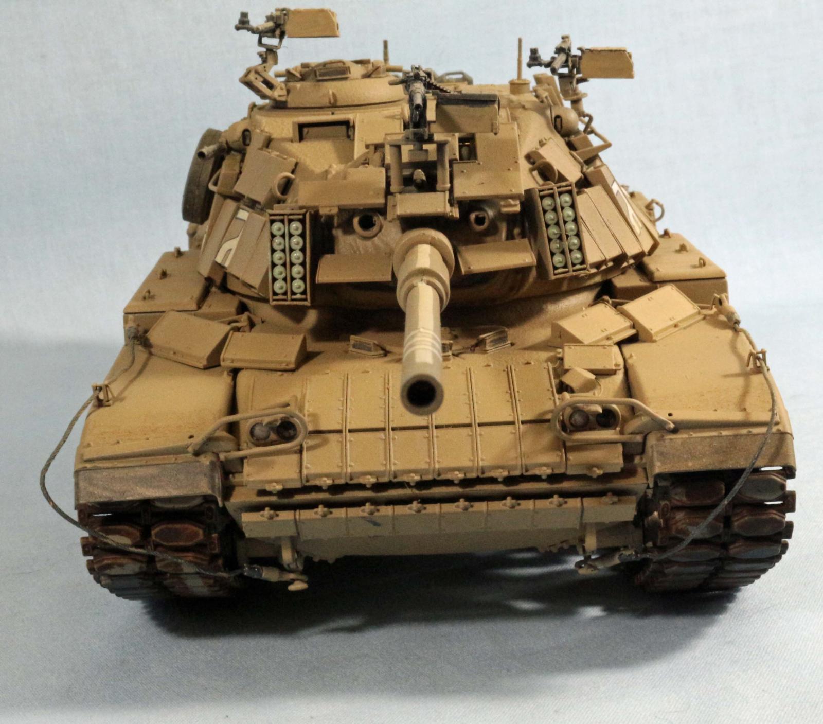
Assembly starts with step 22 where the entire main gun is put together. You have to do this as that is the only way to mount the gun into the tank. It includes the recoil assembly, the breech block and gun mount. The assembly then is glued into the turret, step 23 and the bottom glued on. Steps 25, 26 and 27 has you attaching the gunsight doghouse, hatches, antennas, bustle rack, and grunt rails. Step 28 and 30 has you attaching the turret armor tiles and a few other turret items. Steps 31 thru 35 has you finishing all the rest of the turret attached items and machine guns and mortar. The smoke grenade launchers mount on the front but I had difficulty getting the proper alignment. Due to previous armor tile placement, an alternate might be to put the grenade launcher on first and then the front turret tiles on after as you have more leeway for mounting and fitting the tiles The armor tiles (U10) had the same issue. No surprises. At this point, the turret should be complete
Painting and Finish
Primer and Pre-Shade
I started by applying a primer consisting of Krylon Color Master with Durable ColorMax Technology rattle can (Flat Black) paint. It has great thin coverage and quick drying time. I left it to dry overnight to make sure it was fully cured.
Airbrushing Mission Models Acrylics
I used the premixed MMP-036 IDF Sand grey Version2 for the color coat
Decals
I sprayed a gloss coat on the armor tile on the turret and the gun tube for the decals to adhere to. The decals were fine, they went on easy and adhered no problems.
Details
I went back by hand and painted, the machine guns and the end connectors and center guides on the track, As well as the smoke grenade launchers.
Weathering
A dusting of Vallejo 71.027 Light Brown was used to cut any remaining shine and simulate a coating of road dust,
Conclusion
This kit will build up into a nice representative of an M60A1 based tank as used by the IDF. Due to the part count, it was a challenge but you are rewarded by your efforts
I would like to thank AFV Club for the kit to review and IPMS for the opportunity to review this kit. Thanks for the crew support of the reviewers.


Comments
Add new comment
This site is protected by reCAPTCHA and the Google Privacy Policy and Terms of Service apply.
Similar Reviews