
ICM O-2A (Late Production)
About ICM
ICM is based in Ukraine and offers a variety of modeling subjects including armor, aircraft, and figures. Upon visiting the URL that takes you to the ICM website to view the information on the kit being reviewed, you will notice a button that asks, “You Like It? Find out where you can buy it.” Rely on the information that this link provides in order to find a domestic source for this kit. The $31 price listed in this review is an average price found on a number of source sites.
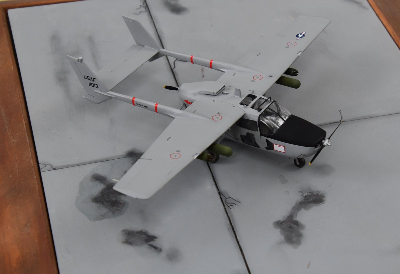
Those who are of a certain age can remember the list of U.S. aircraft that served during the Vietnam War. The O-2 Skymaster is not as well-known as the F-4 Phantom, the F-105, and the A-4 Skyhawk, much less the B-52, C-130, Gunships, and the cluster of helicopters that were heavily involved in the air war, but the O-2 most certainly has earned its place on that list.
The Box
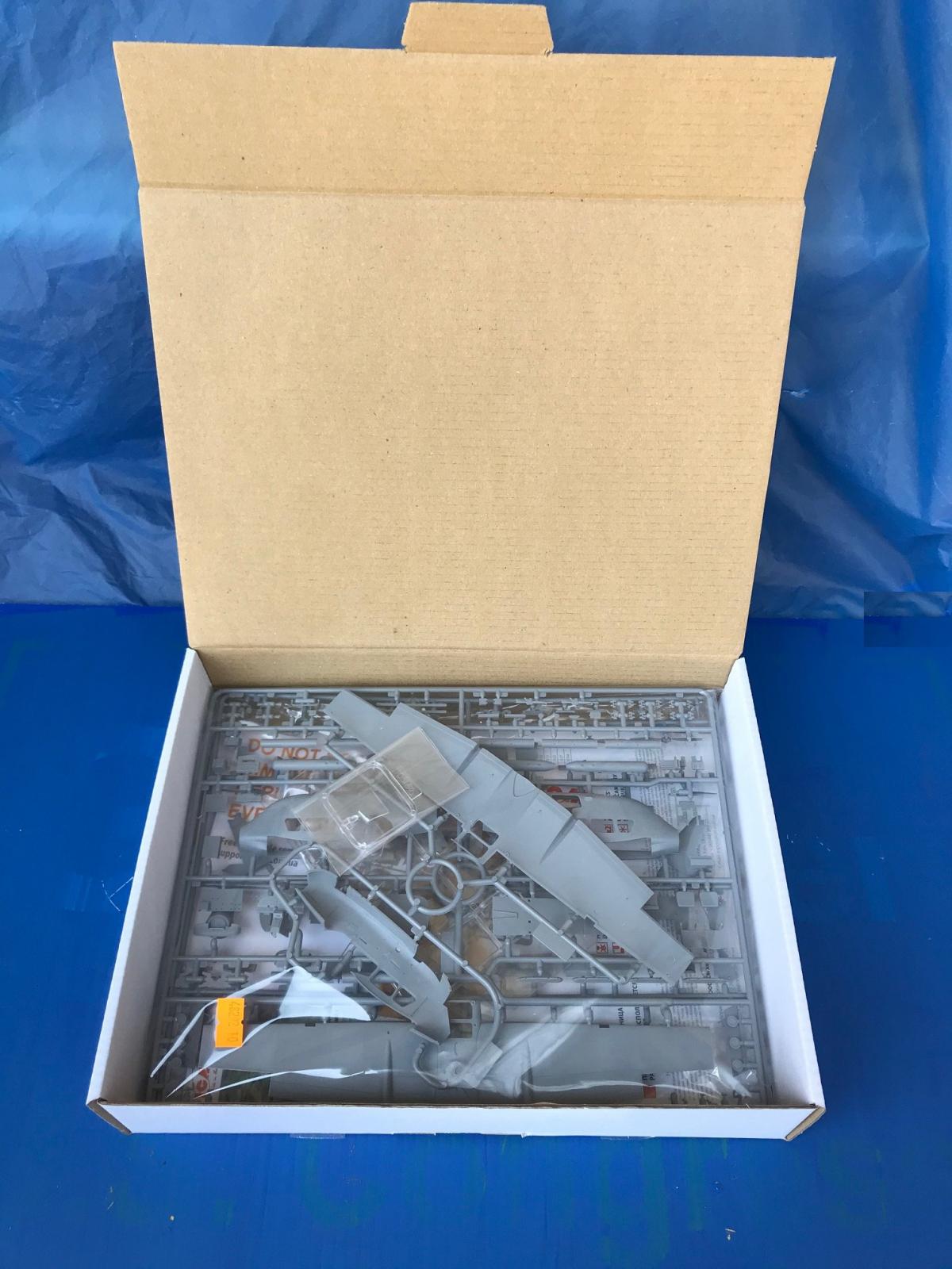
ICM employs a tried and true method of boxing up the kit parts, decals, and instructions. A sturdy cardboard box, with thick sides and a top that hinges open, protects the contents any rough and tumble handling as the product makes its way to countries around the world. One can count on the contents being in pristine condition upon opening the lid to inspect the contents. In fact, I have found other uses for the ICM boxes after the model has been completed. The boxes work well as storage bins for tools, decal sheets, and other models being constructed.
The Contents
Replacement Pledge
ICM includes the Replacement Pledge flyer in every model offered, or at least every ICM model that I have had the pleasure to build. The dog is certainly cute, and the Pledge offer is one of ICM’s way of thanking their customers with product support.
The Instruction Booklet
The first item that one might inspect is the Instruction booklet. The booklet measures out at 8 ¼ inches by 11 ¼ inches. The size of the booklet allows for illustrated steps that are, therefore, detailed, and easy to view. The paper is glossy and sturdy and printed in color. Most of the assembly illustrations are blacklined but the “suggested paints” chart highlights each color listed (in Excel format) with each “cell” highlighted with the color being named. ICM includes paints by Revell and Tamiya. I used Tamiya paints on this project and found that the highlight colors do not exactly match the shade and density of the actual Tamiya paint, but I do not consider that a mistake or an issue. The alpha-numeric labels that Tamiya uses to identify their paints are listed by ICM on the Paint Chart and that is all that is necessary.
ICM uses 9 icons to indicate various actions or instructions on the instruction booklet. 6 of these icons are printed in red and are in small red squares. These 6 icons indicate:
- “Do Not Cement”, “Open Hole” (drill a hole),
- Optional (three different variants, each have slightly different configurations),
- “Used Color” (indicates the Revell/Tamiya colors to be used to paint parts of the model),
- “Make 2 PCS” (when two sub-assemblies are to be built up),
- “Scratch Build”. (ICM uses these same icons for the instructions in other model kits, but for the O-2A the only “scratch build” is the addition of nose weights to ensure the finished model will not be dragging its twin tails.
There are 3 other icons.
- “Assembly Step” - A red circle containing a red number used to guide the modeler in a step-by-step sequence that ICM is recommending the modeler to follow. There are 77 such steps that are illustrated in the booklet.
- “Assembly Unit” identifies a sub-assembly constructed in one of those “Assembly Steps” mentioned above, that are joined to other Assembly Units, such as the engine or the cockpit.
- “Parts Not For Use”- A red square with red highlight filling the square indicates a part not used during the assembly of the O2-A Late Production Skymaster. There are 8 parts included on the runners in this kit that are marked as “Do Not Use”
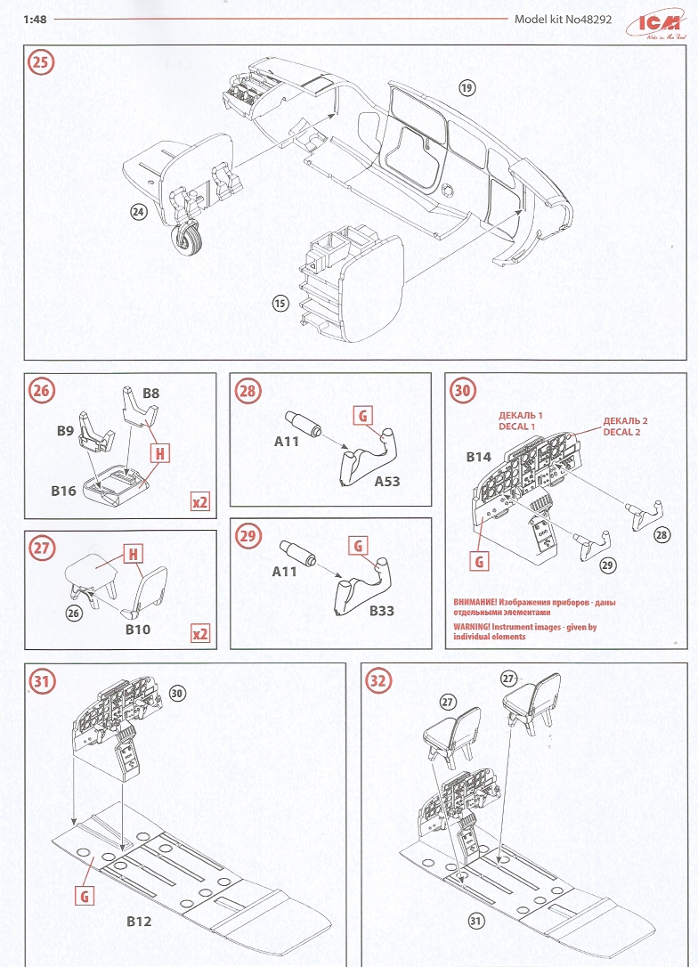
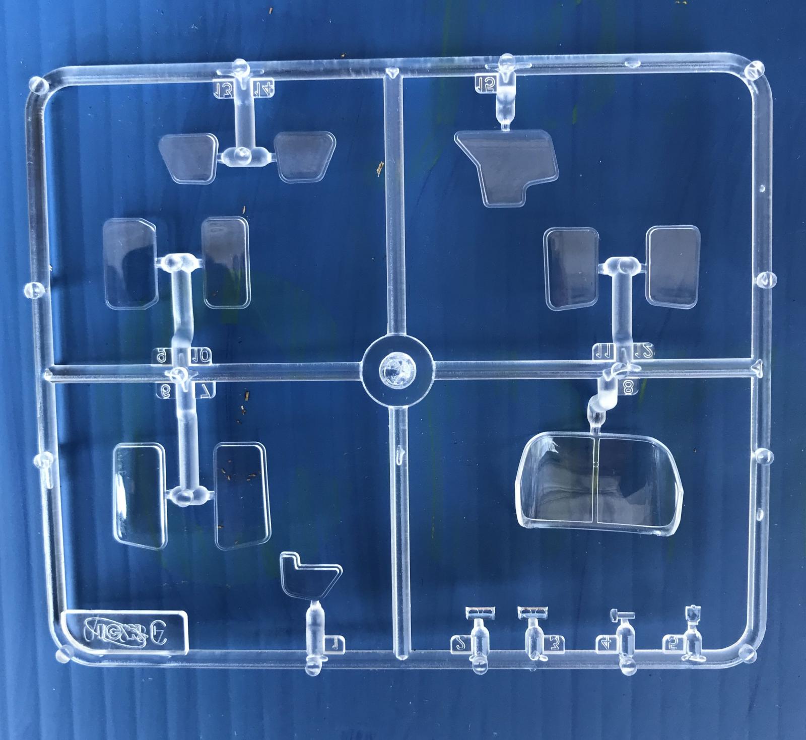
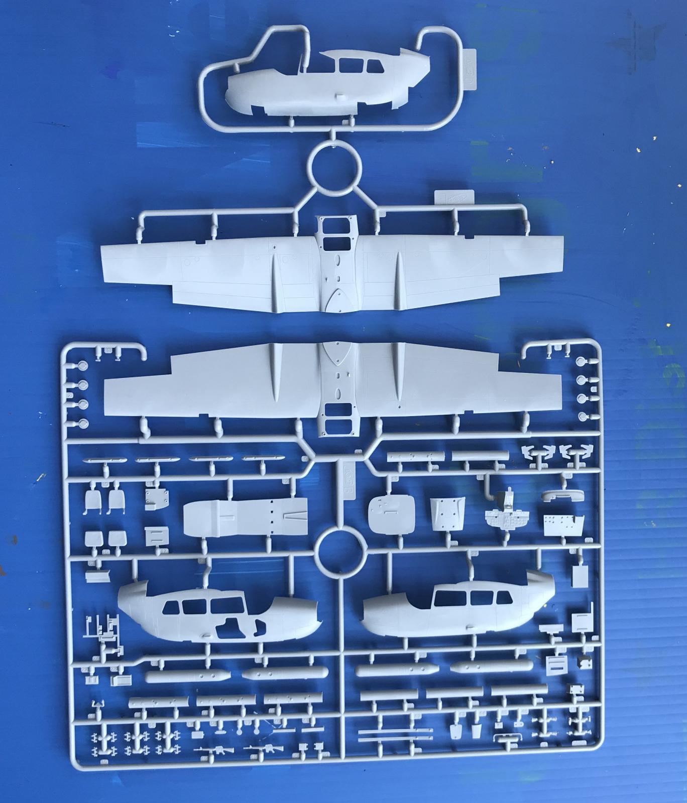
Opening the instruction booklet to page 2, ICM has provided illustrations of each part runner, of which there are six. The 77 Assembly Steps begin on page 3 and terminate on page 16. On page 17 ICM has provided line drawings of masking templates. It is rather easy to cut out the masking templates, place them on the non-tack side of some masking tape, trace around them, and use these home-made masks to cover the windows that are on three sides of the cockpit, actually four sides when one includes the window above the pilot’s head. Pages 18, 19, and 20 contain 3-view illustrations. These illustrations show each of the 3 variants that can be built from this kit. These illustrations use those previously mentioned icons to indicate the paint colors to be applied and decal placement.
Note that you can go to the Product Link provided with this issue and download a pdf file of the instruction booklet.
The Decals
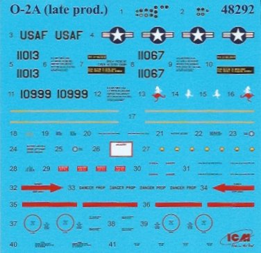
The decals are printed on a decal sheet that measures roughly 4” x 4” (inches). The markings are exceedingly small, but the decal sheet contains all the markings required for each of the three variants that can be modeled. Each decal is numbered, and the Instruction sheet uses that number to illustrate where each decal should be placed on the model. The decals, though tiny, are strong enough to handle a bit of maneuvering to achieve current alignment and placement. I did not use any setting solution. I had airbrushed a layer of Future over the model and that, I think, provided a compatible surface to which the decals adhered nicely. Not all of the decals will be used. Be sure to use the illustrations on the instruction sheet, as well as the molded detail on the aircraft to achieve correct placement.
Assembly Notes
For the most part I followed the assembly sequence recommended by ICM. I did stray, from time to time, when I found that I could knock out a number of the smaller sub-assemblies rather quickly, rather than follow the Instruction’s sequencing to the letter.
There are two tubes, one on the trailing edge of the left wing and a duplicate on the right wing, and I managed to “relocate” both of these tubes multiple times. In the end, I had to replace one of them with some stretched runner. I also managed to “relocate” the pitot tube, under the left wing, and I put it back in a storage container until I was ready to apply paint. Be careful of these tubes or be prepared to reattach them or replace them if the carpet monster demands a sacrifice.
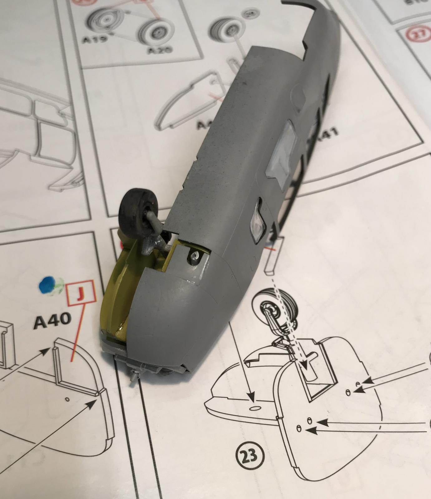
I found what appears to me to be an anomaly in Step 24. The bulkhead, part A40 is shown to have two sets of two holes into which the mounting pins on the rudder pedals are to be located. While the two rudder pedals (parts A1) have two mounting pins, the bulkhead, part A40 has two large locating holes rather than 4 small locating holes. There are two images which accompany this review, labeled “18-A40 bulkhead” and “19-Step24” which show the parts and instruction page. During the time I spent assembling these parts I thought that I had mixed up the parts and had not found the rudder pedals (Part A1) but some different parts that were similar. After some searching, I decided that the error was not mine but rather that the illustration of the bulkhead, Part A40, was simply in error, showing the incorrect number of locating holes.
It was not a major problem. I sanded off the four small locating pins on the pedals and superglued the parts to the bulkhead so that the four locating holes were covered. Nothin’ to see here!
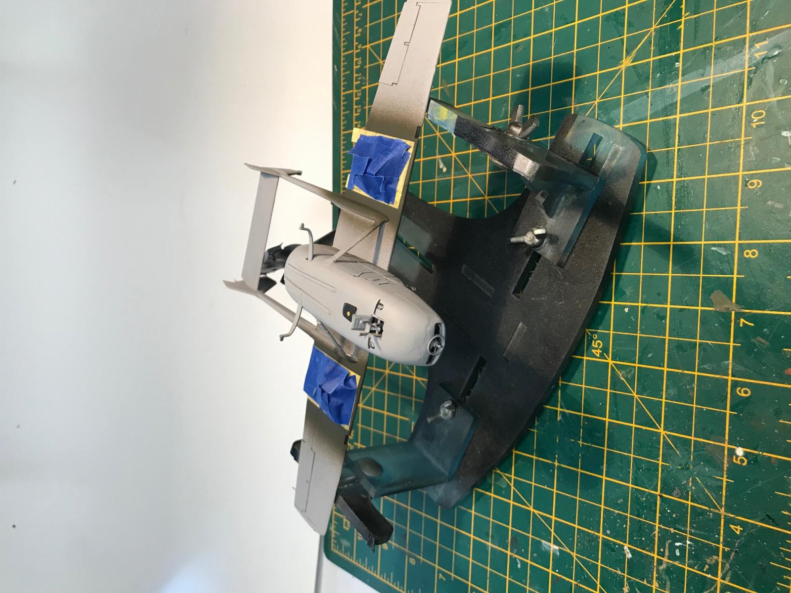
Another aspect of assembly that required some Imagineering involved the same “Assembly Unit”, Unit 24, that same bulkhead and other bits that form the front gear wheel well. Look at Step 24 on page 4 of the instructions and you will see two parts labeled, “A9” that are attached to Part 22. These are exhaust tubes that “exit” the engine exhaust through to two in the bottom of the fuselage. These parts must be glued onto Part 22 at a particular angle so that they align with the holes molded into the fuselage halves. It was rather easy to dry-fit the sub-assembly into each fuselage half, one at a time, and then glue the exhaust tube to the bulkhead, aligning it to the hole in the fuselage half. After about 10 minutes the bulkhead was removed from one fuselage half, dry-fitted into the other, and then the remaining exhaust tube was attached to the bulkhead at the proper angle and allowed to dry.
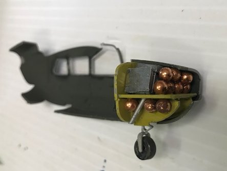
In Step 36, the instructions indicate that 10 grams of “weight” are to be added to the interior area of the nose to ensure that the finished model sits properly with the nose wheel in contact with the display surface rather than the twin tail booms. I used BBs as weights. And to make sure that I had sufficient weight I sawed off (sacrilege!) the back portion of the engine. I took this step after dry-fitting the engine/bulkhead sub-assembly into the fuselage, looking through the engine cowl, also dry-fitted, to see how much of the engine sub-assembly would be visible. Once the surgery on Part48, the engine and bulkhead, was finished I glued it into one of the fuselage halves and loaded the empty space with BBs. I had already done some “balancing activities” to make sure that the BBs would be sufficient to hold the nose down. I’m happy with the results as the model, when it was possible to set it on its landing gear, remained “nose up”.
The final observation regarding assembly is an issue that we’ve all experienced. For those models with a wealth of interior detail and parts, requiring much construction of sub-assemblies that are then glued into one fuselage half or the other, proper location and “fit” of these sub-assemblies are key to having correct alignment when the fuselage halves are united. When assembled, the fuselage halves mated up well, with only a slight gap here or there, that gap due to my own clumsiness and not on ICM’s part. The fit was excellent!
When all was said and done, I spent about 25 hours working on this kit, and probably 5 or 6 hours of that was just watching glue dry.
Conclusion
Considering that ICM products are sold world-wide, the instructions use drawings rather than a written language to guide the builder through the project from start to finish. Studying the instructions, step by step, I have found that there is considerable thought put into the design and sequencing of the instructions and the order of assembly steps. That does not mean that I did not stray from the sequence suggested by the instructions, but I did so after careful consideration. I am impressed with the intelligent approach that is evident in the sequence put forward by ICM.
My initial experience with an ICM kit was some years ago and was satisfactory, but not sterling. Since then, I have had great pleasure and satisfaction in modeling a number of ICM’s figures, as well as aircraft in 1/48th and 1/32nd scales. In my experience with ICM kits it seems to me that the quality of the molding has improved, although my initial ICM experience regarding molding was positive. On reflection, the O-2 kit shows a distinct and noticeable improvement in the engineering aspect of the kit. The manner in which the parts fit together is outstanding. Parts that attach to a piece that has a curved surface, for example, have a beveled edge, the angle of the bevel matching the curvature of the surface to which the part is joined. The lack of flash is another significant and positive feature of the parts in this kit. Kits that have flash tend to suffer from a loose fit of the parts, leading to a seam that must be closed. In the case of the O-2 the fit is excellent due to the lack of flash. The gates where one clips the parts off the runner are designed so that the gate residue can be easily removed without much effort and without damaging the detail which is “local” to the gate.
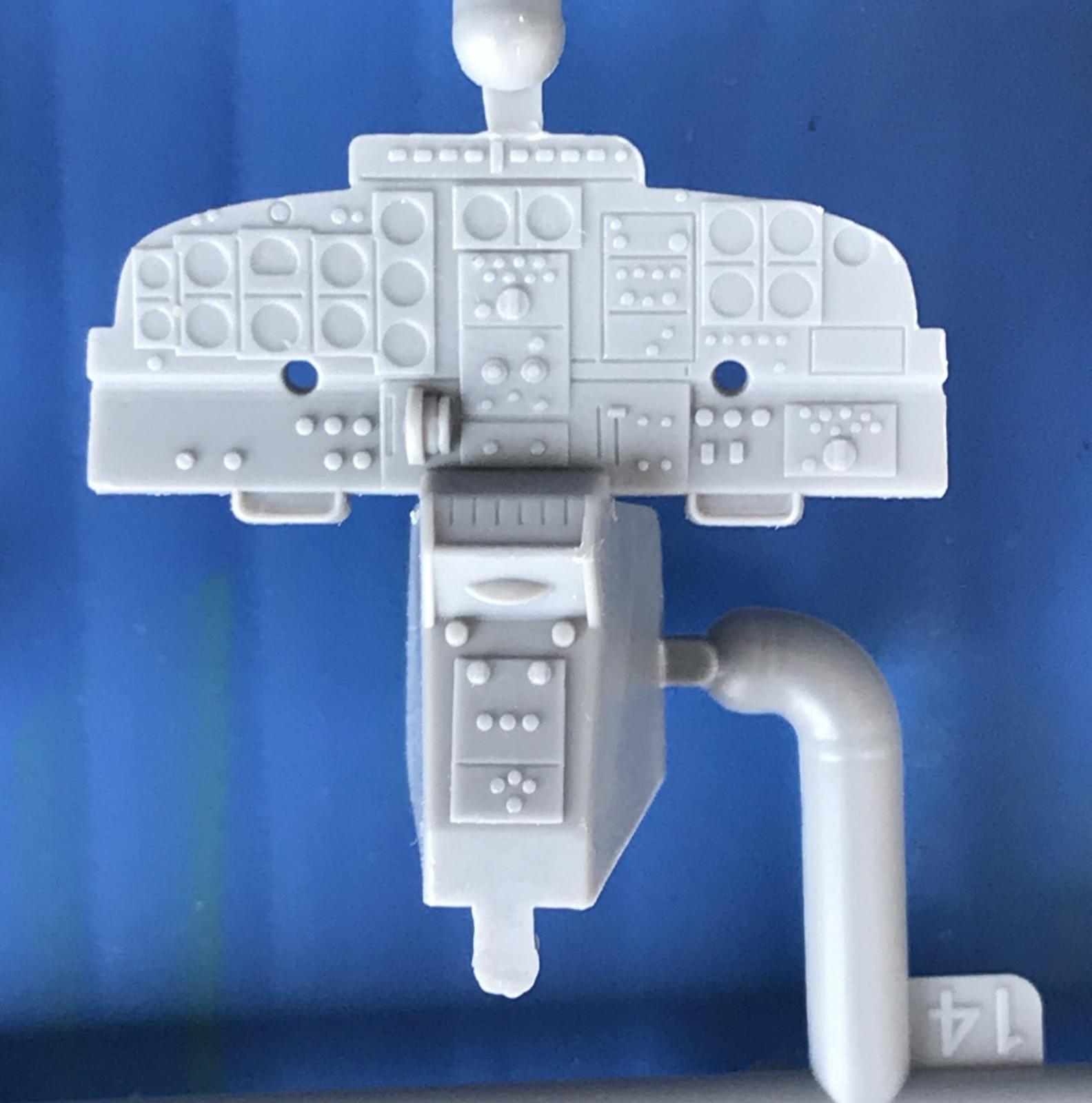
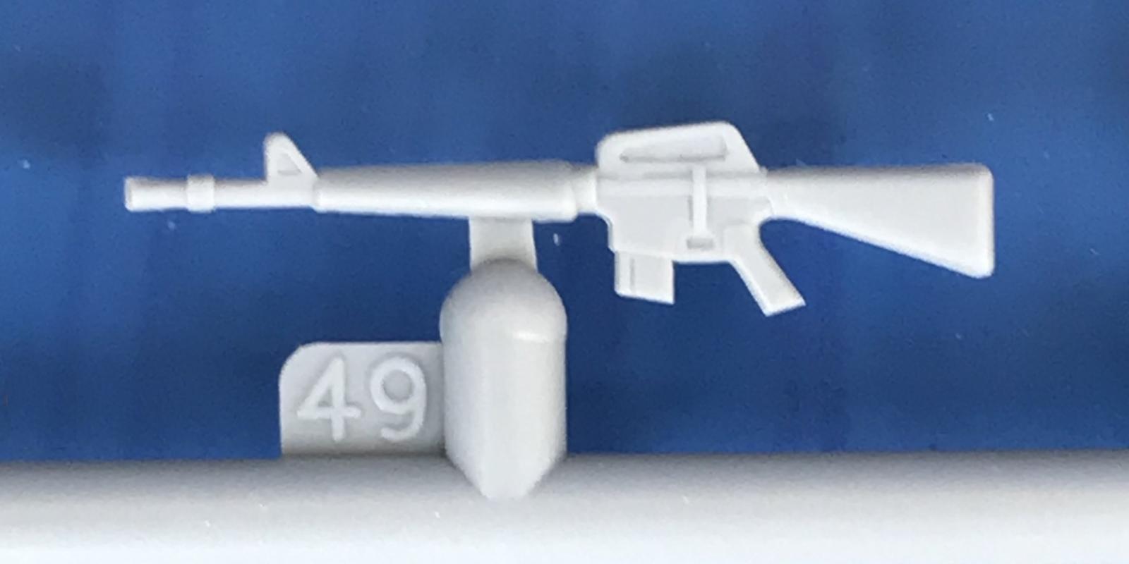
The engraved detail is extremely sharp and clear. It is deep enough to allow for washes and weathering but not overly large. The detail provided on this kit is impressive with a total of 196 parts. The design of the part runners is impressive. Prior to assembly, some of the major parts were dry-fitted. The fit was found to be very well engineered. During the assembly process the assumptions made about the quality of the “dry-fit” were verified.
This kit is highly recommended. Thanks to ICM for providing the kit to IPMS/USA for review.


Comments
Add new comment
This site is protected by reCAPTCHA and the Google Privacy Policy and Terms of Service apply.
Similar Reviews