
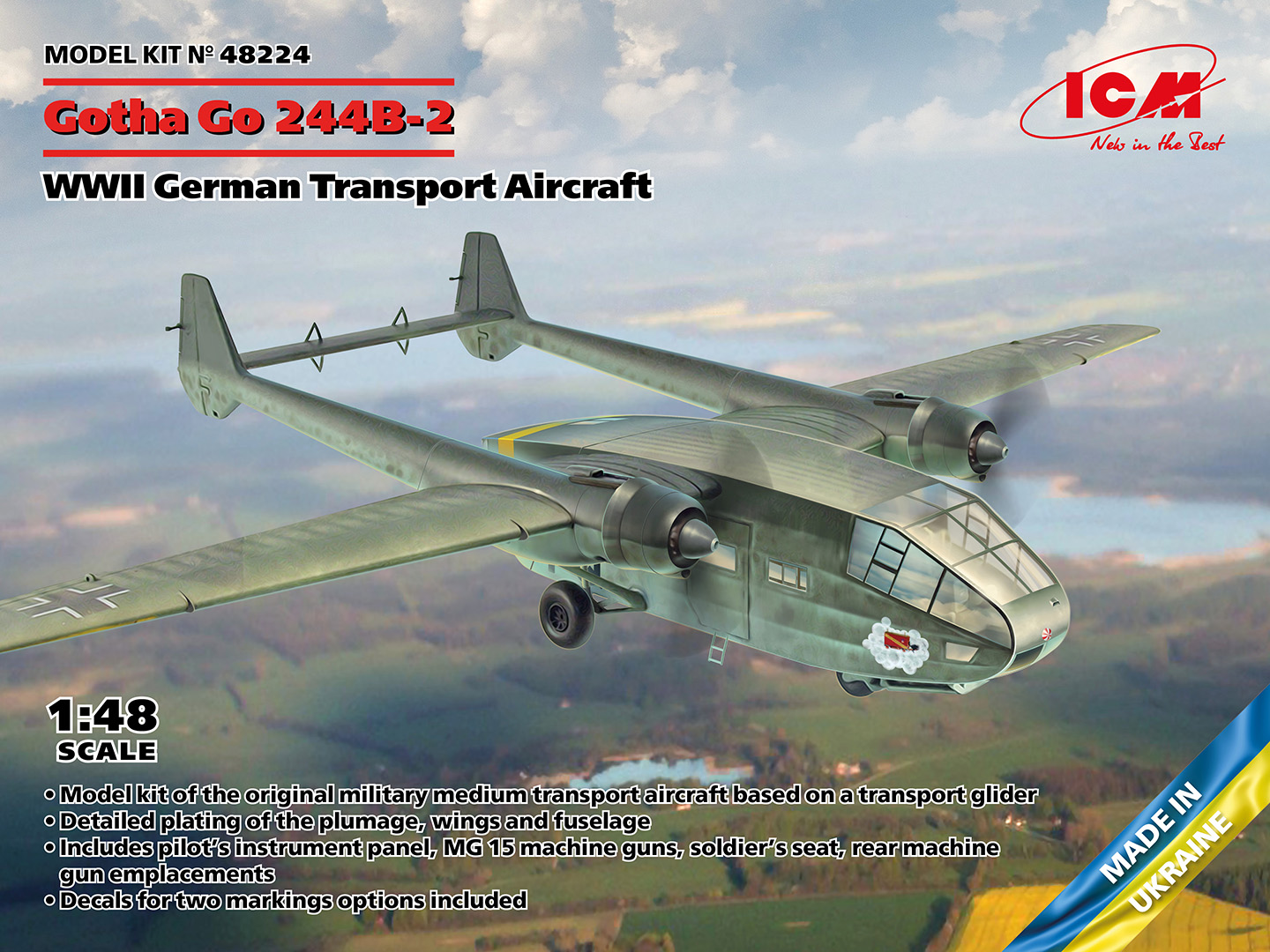
Gotha Go 244B-2 German World War II Transport Aircraft
Brief History - From Wikipedia
The Go 244 was the powered version of the Gotha Go 242 military glider transport. Studies for powered versions of the Go 242 began early in the design of the glider, with one early proposal being for modification to allow a single Argus As 10C engine to be temporarily attached to the nose of the glider to allow recovery back to base after use. This idea was rejected, but the alternative of a permanently powered twin-engine version was taken forward.
Three Go 242s were modified as prototypes of the powered Go 244, fitted with varying surplus radial engines. The first prototype, the Go 244 V1 was powered by two 660 hp (490 kW) BMW 132, while the second prototype had 700 hp (520 kW) Gnome-Rhône 14Ms — and the third 750 hp (560 kW) Shvetsov M-25 A engines, with this model of Shvetsov OKB engine design being essentially a Soviet-built Wright Cyclone American-based nine-cylinder radial. Although only the third prototype offered adequate engine out performance, the Luftwaffe had large stocks of captured Gnome engines, so this was chosen as the basis for the production conversion — usually fitted in counter-rotating pairs in production — although a few more aircraft were fitted with the BMW and Shvetsov engines.
The B series was the main production model, being based on the Go 242B with a wheeled tricycle undercarriage and with fuel and oil carried in the tail booms. 133 were converted from existing Go 242 Bs, while a further 41 Go 244 transport aircraft were built using new air frames, before production reverted to the Go 242 glider version. Plans were also created for single-engined variants with a nose-mounted Argus As 10C or Junkers Jumo 211.
The Kit Contents
Instructions
The instruction booklet contains 20 pages. The first page includes a paint charts for the colors required based on the line of ICM acrylic paints (a small pamphlet is also included listing all the ICM paints in their line of acrylics). Sprue layouts are shown on pages 2-6. Assembly instructions are shown on pages 7-17. There are 101 steps shown with parts numbered and paint colors required.
Page 18 has a layout for mask templates that can be transferred to masking tape. And last color profiles for two aircraft that can be modeled are shown on pages 19 and 20. Both aircraft were stationed on the Eastern Front in 1942.
The ICM web site product page includes a short video showing the step-by-step assembly of the model. This can be a very useful tool when a detail included in the instructions is not clear.
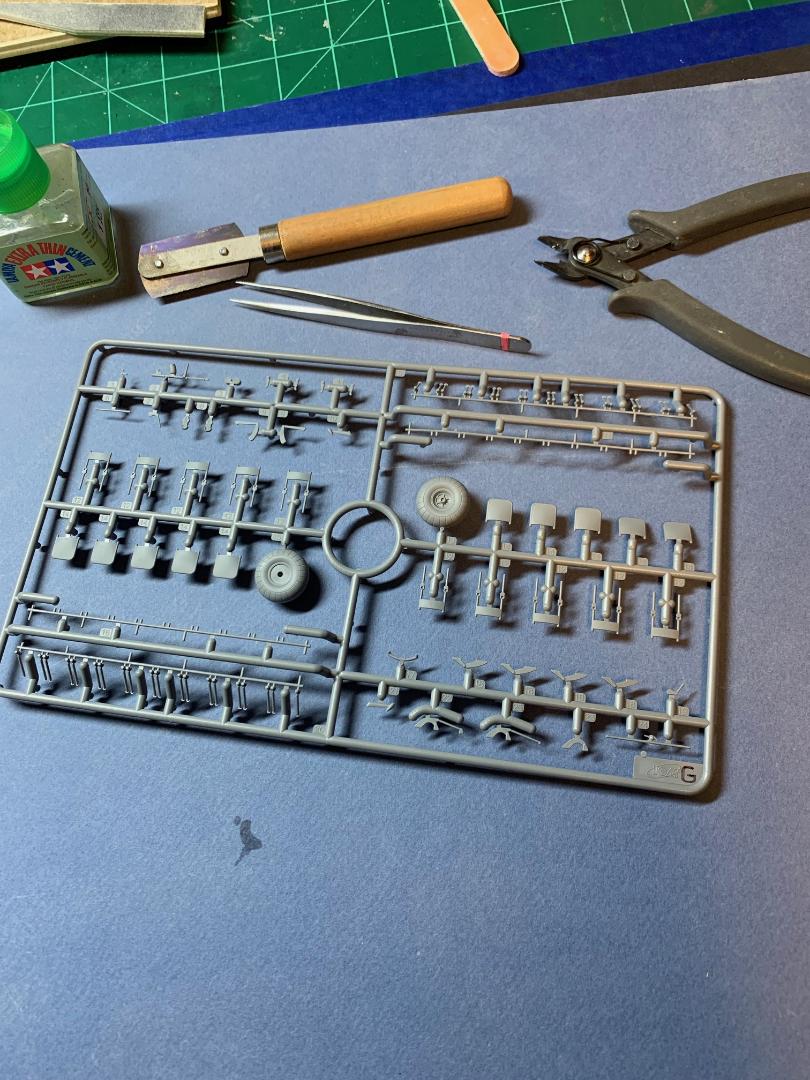
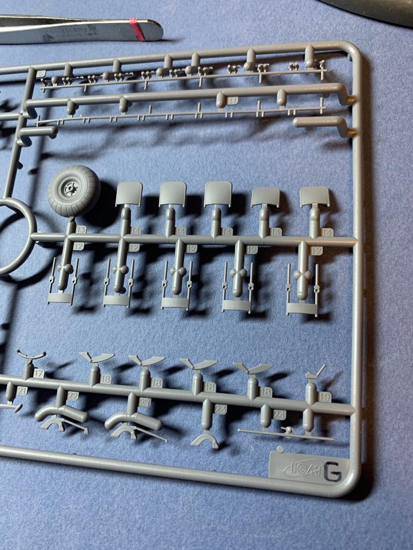
Plastic Parts
The parts are bagged in two clear plastic bags, with a total of 17 sprues. The parts are molded in medium grey, with detail up to the usual quality standard shown in recent ICM kits..
Weapons
The weapons consist of hand-held machine guns (not used in this build).
Clear Parts
The clear parts are on a single sprue, crisply molded and are quite clear. I normally dip clear parts in Future prior to installation, but here the parts were so clear I did not bother.
Photo-etch
None included.
Decals
A small decal sheet is provided for the two subject aircraft.
Construction
Cockpit/Front Section Interior
The assembly is detailed from step 1 through 31. Clear parts placement is covered in steps 32-35.
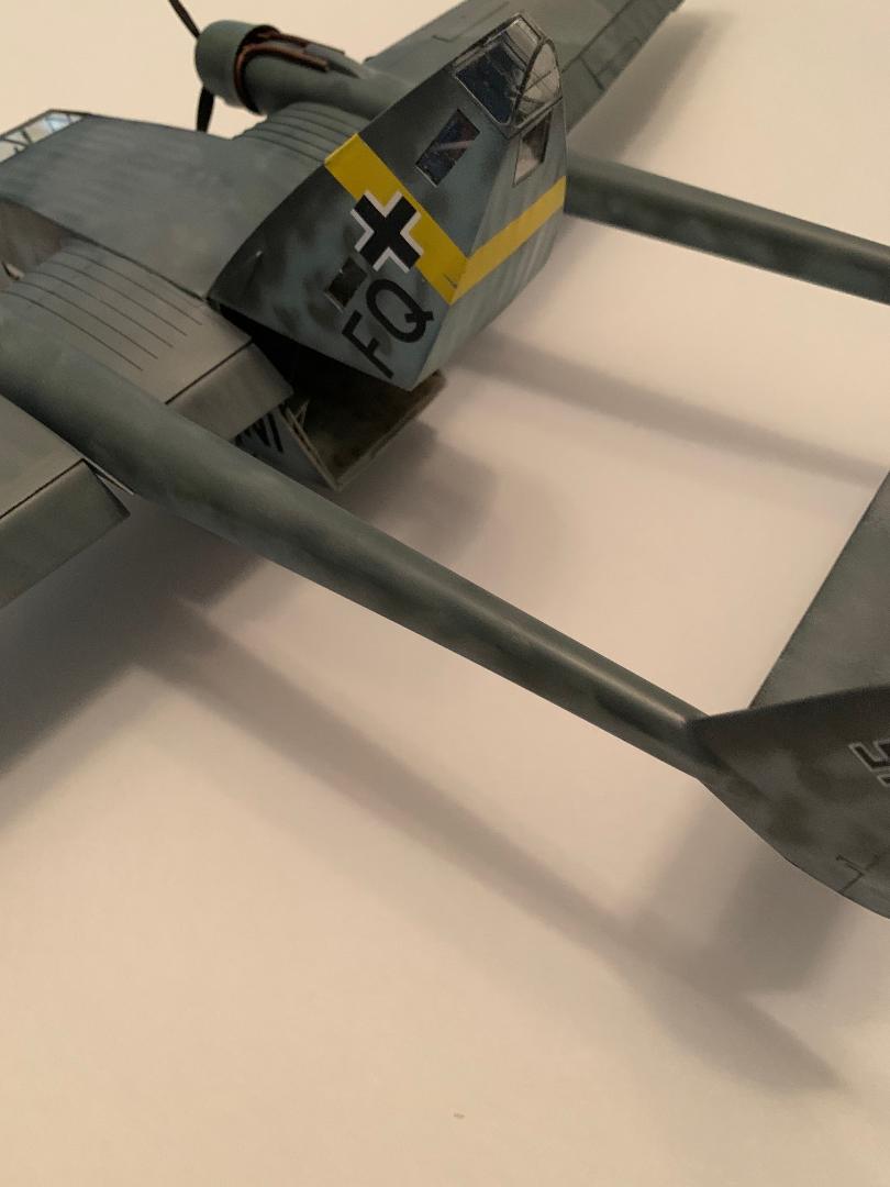
The fuselage forward section floor is first and is comprised of two floor panels and the fuselage underside. The floor panels are guided in place by two small nubs that fit into sockets on the underside of the two panels. It should be noted that the Gotha Go 244 has a fabric skin covering over a tubular frame. The fabric is beautifully replicated on the exterior side of the parts. Step 2 details the assembly of the tubular frame, with step 3 showing the sub-assembly fitted to the floor. There were potentially too many moving parts in step 2. It would require more hands than what I had available, so I deviated from the instructions. I glued part D23 (the wing spar and rectangular frame) to the floor. Then I glued the two side tube frames to the floor panel edge and the rear square frame. Part E20 has a top and bottom which I was not aware of until I tried to fit it in place. Once I recognized the necessary orientation the part fit like a glove. Once this forward interior section was completed I set it aside overnight to allow the joins to harden.
Next comes the passenger seating. There are two rows of seats, ten per side. Each seat is made up of two parts (the seat cushion and the backrest), and finally the floor and side wall mounts. The seats and backs have concave cushions, so care is required in the fit. The long tube frame wall and floor supports will also require care when removing from the sprue and during the assembly. However, everything fits with minor adjustments. Once the two subassemblies are completed they may be glued in place. I held off until the interior and seating were painted.
Front Fuselage Exterior
The two side panels for the forward section of the fuselage slide over the wing spar and snug up against the interior assembly. Something was off here. The bottom join of the side panels did not align with the floor panel. They were about 1/16" off (too far back). After some thought I decided to cut the two spars off, fit the side panels in place and apply the solvent I would then glue the spars back in place and fit the wings once the new spar location joint had hardened thoroughly.
Fitting the two front fuselage sides to the assembled interior tubular frame proved to be a bit challenging. There are two vertical members that fit into a vertical slot and opening in the side walls. It was difficult to align the parts and glue them together. I started with the right side and once that was fitted and glued I added the bottom panel. I had to apply the solvent from one end of the join to the other in a progressive application while holding the parts together as the solvent set up. I glued some lead weight below the floor of the cockpit as this model has all the makings of a tail-sitter . The roof panel was next set in placed and solvent applied. It was a repeat performance for the left side. At this point I set everything aside to harden over night.
Wings / Engine Nacelles
This work begins with step 36 and in completed with 53.Each wing is comprised of a top and bottom, plus the separate two-part flaps/ailerons. once the top and bottom parts are fitted together the assembly is slid onto the wing spar on the side of the front fuselage. The spar did not fit into the wing slot, and I saw that the spar was too tall. Scraping and sanding reduced the height so the wing eventually slid in place, making sure the wing top matched the fairing on top of the fuselage.
The flaps/ailerons may be installed in a neutral or dropped configuration if desired. I found very few images of the Go 244 on the internet. I did find one image that showed all three flaps in a lowered position. That's what I did for this build. I added a small weight to the forward end of the bottom part of the engine nacelle that is formed over the wings.
Rear Fuselage
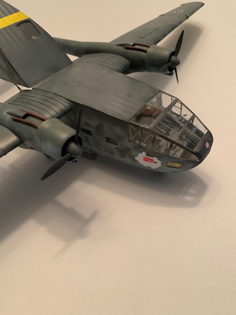
The rear portion of the fuselage that lifts for access to the passenger and storage area in detailed in steps 54-67, with step 68 depicting the lift section in a lowered configuration. The parts fit together reasonably well (somewhat better than the forward fuselage), but care is required during the assembly. Go slow, test fit and follow the instructions, My only deviation from the instructions was to leave the clear part off until the interior surfaces were painted.
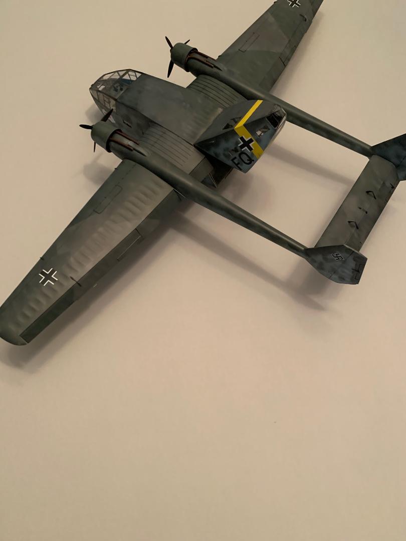
Being somewhat adventurous I decided to fit the rear fuselage in an open configuration. The plastic supports provided in the kit were too flimsy in my opinion and I decided to used .07mm OD brass tubing for improved rigidity. The tubing was cut to size, painted and fitted in place with super glue. These supports were added once the model was painted ad decaled.
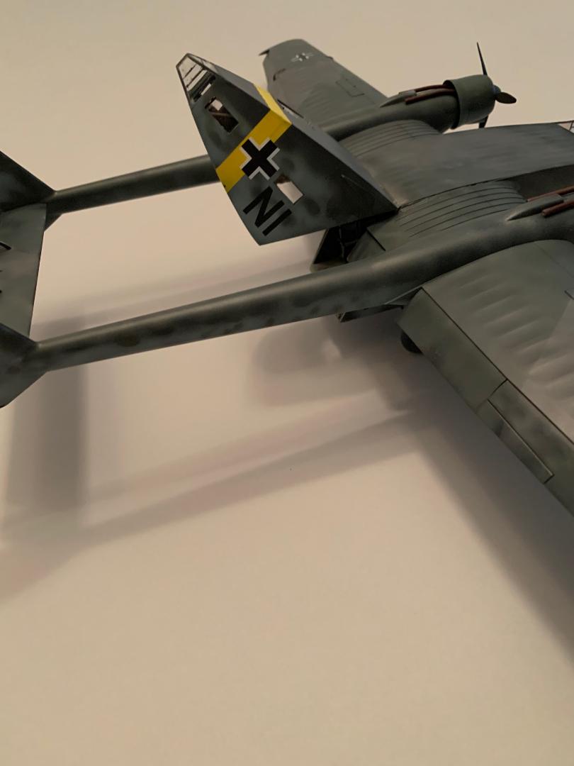
Tail Booms
Steps 69-76 detail the assembly, with step 85 showing the fit of this sub-assembly to the wings. Alignment was superb.
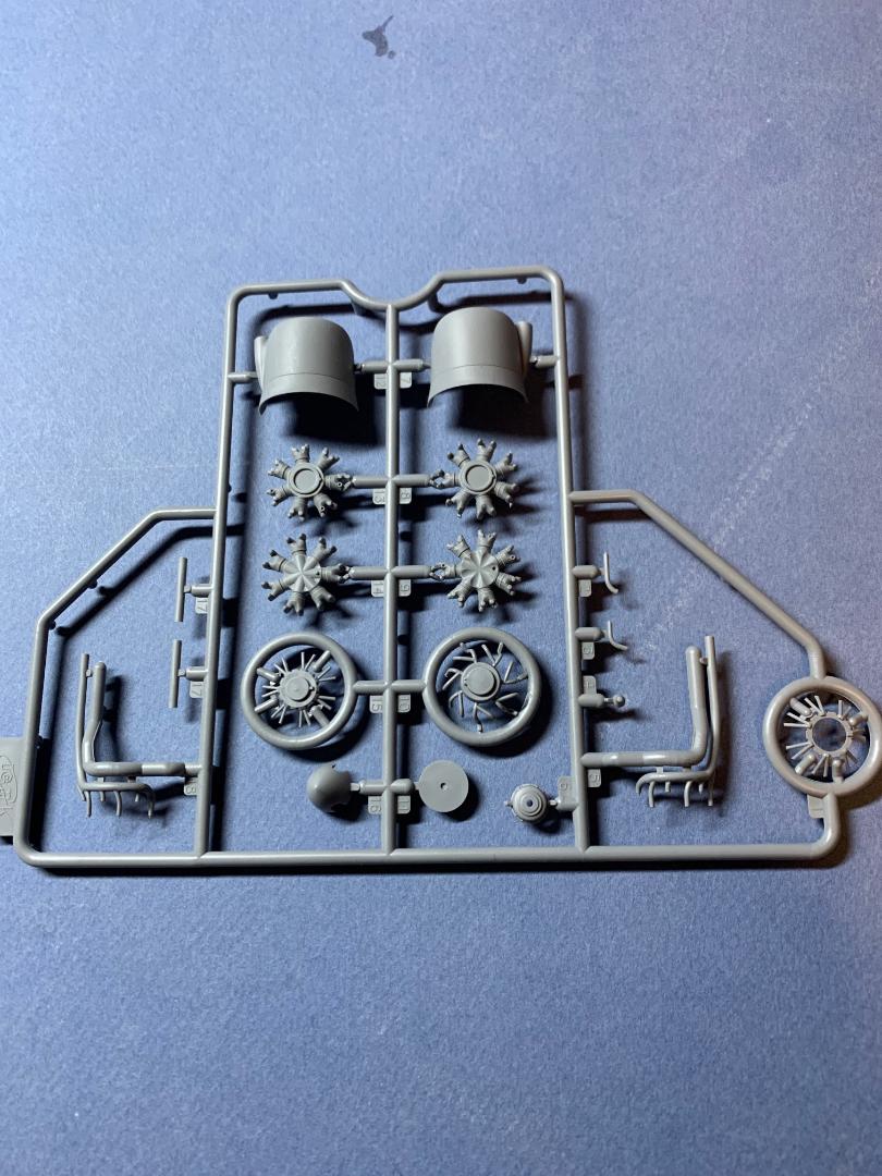
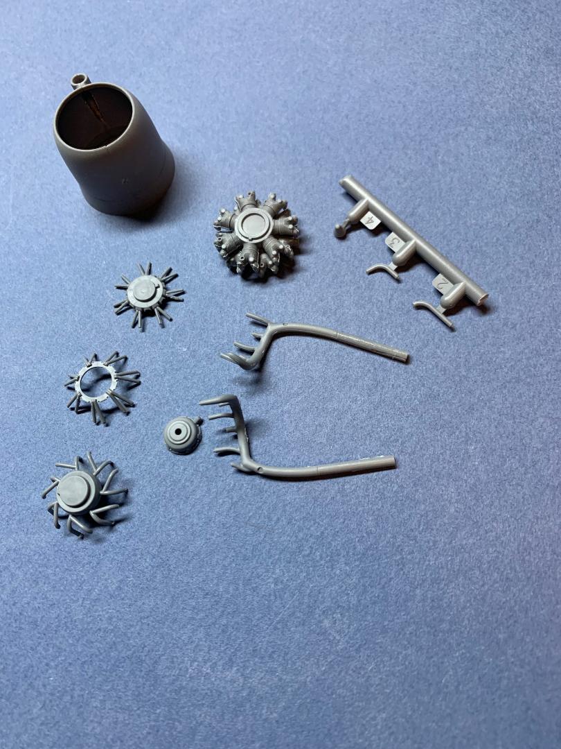
Engines/Exhausts
The engines and cowlings are assembled with steps 77-85. Each cylinder bank is made from front and rear halves that must be lined up properly before the solvent is applied. A separate exhaust collector is attached to the bank side of the assembled cylinder bank. The ignition harness is also two parts that will require care to remove from the sprue. The exhaust discharge is made up from four parts that will require some careful alignment with the exhaust collector ring before the solvent cures. Each long exhaust pipe has a recessed opening in the end for some added realism.
The engine cowling are made from two halves, with the instructions showing the completed engine assembly being trapped betwen the two halves and solve applied. I test fitted the engine with the dry fitted cowlings and since they fit I glued the cowlings together and fitted the completed and painted engines in after the joints were sanded smooth. I planned to fit the finished engine/cowling assemblies in place once the model was finished and painted.
Landing Gear/Wheels
Steps 86-91 detail this work. Each wheel is two parts and when fitted togther the solvent was applied and the join line pretty much disappeared. Although the instructions do not offer a color call out for the wheel hubs, the color profiles appear to indicate the hubs are the same "pale blue" as the undersides.
The nose gear is shown trapped between the two parts of the gear housing. I preferred to paint everything separately and rather than try to paint the nose wheel in place I drilled out the center on the nose wheel and the gear housing attachment points and added in short length of brass tube to act as an axle.
Finishing Touches (AKA the small parts)
Steps 92-101 show the placement of the remaining small parts, including the assembly of the propellers.
Painting
Masking the Clear Parts
I made a copy of the masking templates to preserve the original and used the copy to cut masks from Frog Tape, the yellow version. This is a tedious task but worth the effort as many of the clear parts are unusual shapes. I used a glue stick to adhere the paper template to the tape and once the mask was cut I removed the paper from the tape. Eduard supposedly will have a set of pre- cut mask early this year. The clock was running on my review and I could not wait.
Each mask is numbered and there are four layout drawings that help to locate each mask on the model.
The Interior
As noted above the interior was painted as the subassemblies were completed. I used Tamiya XF-22 Grey Green.
Preparation for Painting
The model was first washed in warm water with a drop of Dawn detergent added and lightly scrubbed with an old tooth brush. It was given a rinse of warm water and set aside for a day to thoroughly dry.
The Exterior Surfaces
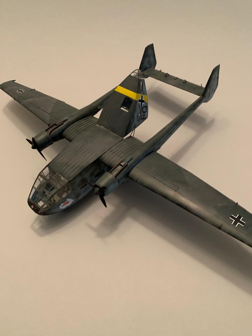
The exterior was first primed with Tamiya XF-1 Flat Black which was then marbled with Tamiya XF-2 Flat White. The undersides wingtips and aft fuselage theater band was painted with Tamiya XF-3 Flat Yellow after a primer coat of flat white. The undersides were next painted with Tamiya XF-23 Light Blue after the yellow areas were masked. I used Vallejo Model Air 71.259 RLM 75 and 71.258 RLM 74 for the topsides.
Engines/Exhausts/Propellers
The engines and exhausts were first painted flat black, then given a coat of Alclad ALC-101, aluminum. The cylinders were given a black wash to bring out the detail, and the exhausts were given a coat of Alclad ALC123 exhaust manifold.
Landing Gear
The landing gear was painted underside blue. The nose gear was fixed in place after the wheel was installed.
Decals Application
Once the painting was completed the model was set aside to allow the paint to thoroughly cure. Alclad Aquagloss was applied and allowed to cure for 48 hours. I used the markings for the 106 Special Purpose Battle Groups (KGr.z.b.V 106) Kirovohrad 1942. The decals are quite thin and were quickly loosened from the backer paper after a dip in warm water. Each decal was carefully slid into place on the model. MicroSol and Microset were used in the placement. The carrier film was almost invisible. Once the decals were completely dry and settled in place a coat of clear flat was used to seal everything in place.
Reviewer's Notes and Comments
I used Tamiya thin cement for this build, and the plastic responded well to this solvent. The tubular frame parts have attachments molded very close to the sprue runners. I used a micro saw to cut the attachment points, being very careful not to stress the frame parts while they were being cut free. These are quite delicate and care is required during the removal process. Sprue cutters were often used to cut the runner to allow access for the saw blade in some instances. The attachment sprue required careful sanding. The plastic ICM uses in their kits is somewhat soft. None broke during removal or placement.
If I were to build this model again that are a few things I would do different. For example, I would glue the floor (part C5) to the right side (parts A3-2 and F1-6) and assemble the interior tube frame first aligned with the wing spar frame and side wall slot. The left side (parts F1-8 and A3-3) should then fit in place nicely.
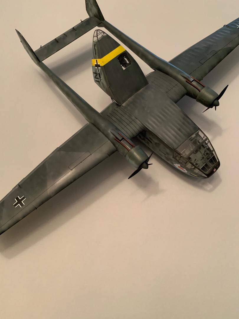
Conclusion
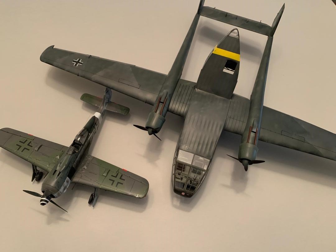
The finished model is large, approximately 13" long with a 20" wing span. I have built a number of the current ICM kit, aircraft and military vehicles. Those kits all have several features in common: amazing detail, generally great fit and outstanding engineering of all the parts. Not to mention lots and lots of parts. This kit is certainly not for the beginner. there were a few minor glitches during construction but nothing that could not be overcome. A few parts in the instructions were numbered incorrectly, but again nothing of consequence. I was challenged by the complexity of certain sub-assemblies, but thoroughly enjoyed the build.
I wish to thank ICM and IPMS USA for the opportunity to build and review this kit. I highly recommend this kit for the experienced modeler.

Comments
Add new comment
This site is protected by reCAPTCHA and the Google Privacy Policy and Terms of Service apply.
Similar Reviews