
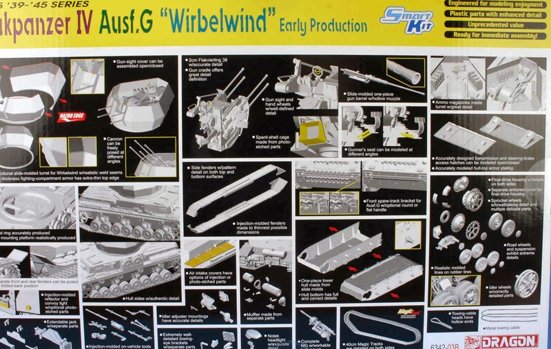
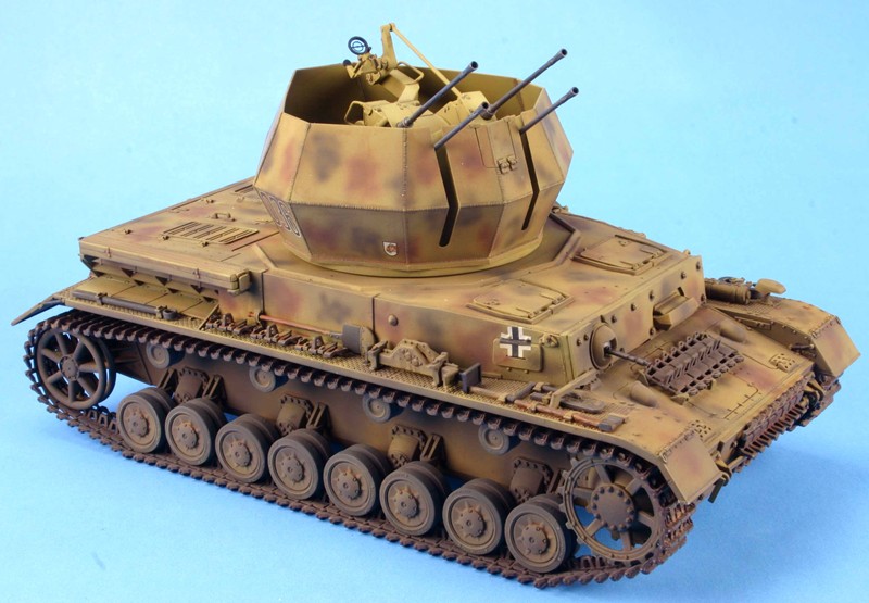
Flakpanzer IV Ausf G "Wirbelwind" Early Production
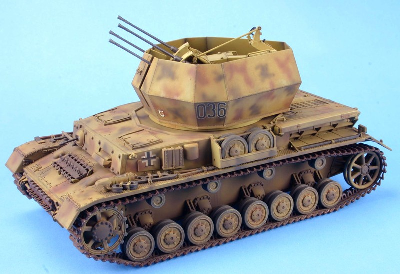
The Flakpanzer IV “Wirbelwind” (German for whirlwind) was a self-propelled quad 2.0 cm anti-aircraft gun based on the Pz IV. It was developed in 1944 as a replacement for the Mobelwagen. The Wirbelwind was replaced by the Ostwind with a single 3.7cm FlaK 43. The number of units produced ranged from upper 80’s to approximately 105.
This is a multimedia kit comprised of 500+ styrene parts, magic tracks, one braided metal wire (which is very stiff even after annealing), one photo etched fret, decals and the set of instructions that need to be reviewed very carefully before gluing any parts together.
Most Dragon models today are a collection of old sprues and new sprues added to create a new kit variant. In this case, Dragon has done so and you will have some sprues with the same letter. Even though Dragon has not advertised this is a 2-in-1 kit, you have many options that need to be reviewed and decided on before you start this kit.
Step 1. This step is the assembly of the idler wheel, drive sprockets, road wheels and return wheels. There are no problems here other than the removal of the mold line which is noticeable on the road wheels.
Step 2. This step is the chassis build. There are 4 mold stubs on the top of the chassis tub that need to be removed, but this is not shown in the instructions. If you don’t remove these stubs the fenders will not fit. Here is the start of your decisions; you have a choice of three rear plates (E26, E27, and E37). There is no right or wrong here, so I chose the one that had the most detail on it (E27). The next choice is between the plain additional armor plate (E4) and the bolt on additional armor plate (K8). I chose the bolt on plate, again for more detail. You then get a choice of two different styles of towing pintles, round handles (A31) and flat handles (A30). If you are making a specific model check your reference photos for the appropriate style. I do suggest that you make sure the pintles will fit into the holes in the tow shackle by test fitting and drilling out the hole if they don’t fit. You need to do this now, as the shackle is hard to reach when the drive sprocket and fenders are installed later on.
Step3. In this step the running gear mounts and stops are installed. This is straight forward and did not have any problems.
Step 4. This step is the detailing of the rear plate. You will need to choose which rear towing shackle you will want to use. Your choice is plain (H45), with bolts (H49), and with extension (H23). I chose the mount with the extension. On the rear plate (E13) there is a hole in the plate on the left side. The instructions do not show this hole nor is there anything inserted into it later on in the instructions. I suggest that you fill this hole now before too many other things have been added and make accessing that area difficult. You may want to leave the muffler off until later after you have painted the chassis and muffler separately.
Step 5. This step builds the hull machine gun, the transmission cover plate, the bolt-on armor plates and the spare tracks to be on the transmission cover plate. Here you start with the assembly of the machine gun. The gun is well done, but you can’t see any of it other than the barrel that projects outside of the hull. Now you must choose between two styles of transmission cover. The difference between the two is how the armored splash guard is installed. If you are going to use the spare tracks on the transmission cover plate, you will need to drill out the holes so the spare tracks can be glued in place. Here you will also need to decide to use the plastic or Photo-etched spare track holders. I left these off till the very end as I wanted the camouflage paint to go under the spare tracks. The rest of the step is to decide on the additional armor plates. The choice is between plain (E1, E2) and bolt on (K9, K10) I chose the additional detail of the bolt on type.
Step 6. This step adds the running gear and transmission plate to the hull chassis. No choices here. I suggest that you not glue the idler wheel and idler wheel axle to the hull at this time. I waited till I had mounted the tracks and then used the idler wheel as it was intended to take up any slack in the track to give the correct tension (or lack thereof).
Step 7. This step installs the internal mount and flooring for the Flak gun. I could not figure out how the flooring (D13) properly fit into the hull. I nibbled away at the side that butted up against the hull until it allowed the part to sit flat on the floor. From there I installed the firewall (D16) and a T support (D24). This was followed by the fenders. You will need to choose between the Notek and Bosch light as you will need to drill out different holes depending on the choice you make. After the fenders are installed you will place the actual gun mount supports in place. The instructions now call for the upper and lower spare track brackets to be glued into place. For ease of painting I only glued in the lower bracket (H43) now and painted the tracks separately and added them and the upper bracket (H60) at the end. This step also includes the tracks.
These are Magic Tracks that require no cleanup unless you want to remove the ejector pin marks on the inner face of each track. These appear to be the proud type that will clean up with a swipe of the sanding stick or a sharp blade. These are not workable tracks so you will need to glue them together.
The method I use to glue the tracks together is as follows:
- I use a track jig that is adjustable. I place it on the work surface and put a strip of yellow Tamiya tape down with the sticky side up. If you don’t have a jig, you can use a ruler. Just tape it down and use it as a guide to keep the tracks straight.
- Then I “assemble” the track using the jig and tape to hold all the parts in place.
- I prepared the tracks one side at a time by adding a dab of Tamiya thin glue at each joint and letting this set for about 3 to 5 minutes. This will allow the glue to set enough to hold the tracks together but still be flexible enough to put sag into the tracks.
- Here I used a new tool from Hobby Trax, Part number HT 007. This is a track form that allows you to drape the glued, but not yet set, track around it. I taped the tracks down to the form to ensure the sag will be formed into the track.
- Let them dry.
- Remove the tracks. Paint and weather them off the vehicle.
- Mount the tracks to the model, along with the drive sprocket and idler wheels.
- When you are happy with how the tracks look on the model, glue the drive sprocket and idler wheel into their permanent position. Make sure that the tracks are correctly aligned. As one of the biggest mistake armor modelers make is to have tracks that are toed in or out caused by the improper alignment of drive sprockets and/or idler wheels.
Step 8 & 9. These two steps build up the casement side walls. In step nine the instructions for mounting the shovel are pointing to the wrong locating hole. The correct hole is the lower set. Also pistol port plug (K12) is shown in place, but not actually called out until step 13.
Step 10. This step starts on the rear deck with the two access hatches. Here you add the interior slates in either the open or closed position. Now you have the choice of two different styles of air intakes. Here I chose the style with more detail. The last item in this step is the two tow cable support rods are to be installed. Past experience with these two pieces breaking off during handling, has me leaving them off till the very end. I did have some problems with the wire for the tow cable. It is very stiff and even after annealing the wire it was difficult to bend. The instructions suggest that the wire be cut to 150mm in length. I found that to be too long. I suggest that you glue the loop (A20) onto one end, then bend the cable to the desired position, then see where you would need to cut the cable and glue on the second loop. This will allow for a better fit on the support rods.
Step 11. This step installs the casement and upper deck to the hull. Here you will be adding several subassemblies from prior steps. Make sure you test fit before applying glue.
Step 12. This is where you attach all the little items to the left fender. You do have a choice of Styrene air intake covers (E22) or Photo-etch cover (MA1, MA2, MA7, and MA3). There are two styles of convoy lights (G13 & G16) pick one, and a rear reflector in styrene (H18) or PE (MA13). The instructions show a handle installed just before the air intake area, but do not call it out. It is part E17. Generally I leave most of these items off and paint them separately and add at the end of the build.
Step 13. This step is a basic repeat of step 12 except for the right fender. The only new choice is between styrene fender support (H5) and PE (MA12)
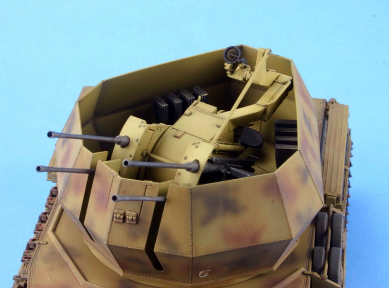
Step 14. This step starts the assembly of the quad gun main unit. The only option here is the use of PE for the gunner seat support rods. If you use the styrene part (A15) the seat can only be displayed in the down position. If you use the styrene part (A58) and the 4 PE rods (MA31) you can display the gunner seat in an up position. If you are careful in the assembly of tube (A48) the gun tubes can be positioned as desired.
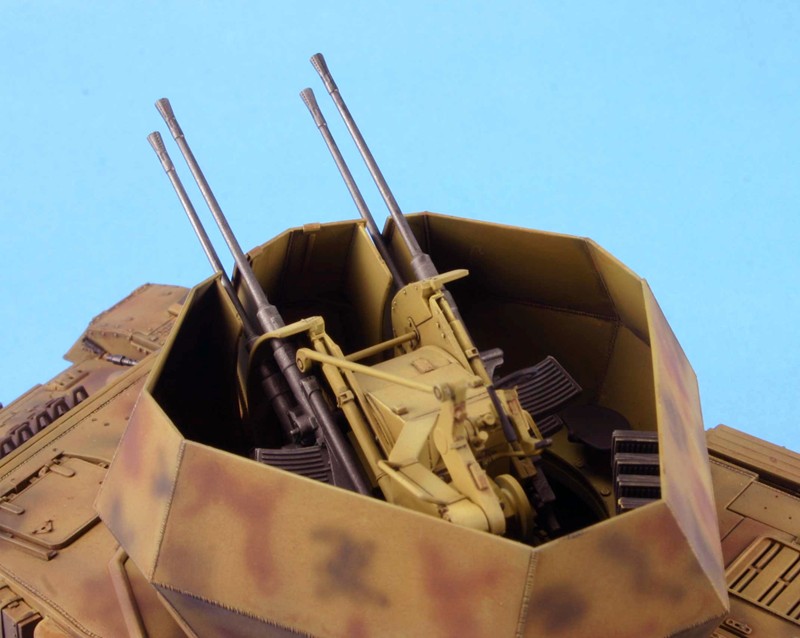
Step 15. This step builds the outer portion of the gun along with the 4 guns. I did not attach the guns now so I could paint and weather the mount without the guns being in the way. The guns were painted with Testors buffing gunmetal.
Step 16. This step brings the subassemblies from step 14 & 15 together to make one unit. There were no issues here.
Steps 17 & 18. These steps build the gun shield tub and add the seats and extra ammunition rounds. The only real care you need here is to make the two halves of the gun tub (C1 & C3) match up. If this is done properly you can’t tell where the seam is.
Steps19& 20. These steps add the gun mount to the gun tub. I actually mounted the empty gun tub to the hull, and then added the gun mount.
Step 21. This step adds the two spare gun barrel boxes to the hull. You can leave the box open and show the spare barrels. These did not look all that good. If you want to leave the boxes open I suggest that you get some aftermarket barrels and build a full depth box for showing them off.
Accuracy: The drawings found in the references listed below show the kit to be basically accurate. Since I’m not a rivet counter I don’t go beyond that. I model for fun.
Molding: I found the molding to be clean, with no sink marks and few ejector pin marks. The mold seams were easily removed and I saw no flash. Dragon makes extensive use of the pin nodes to keep ejector pin marks on the parts to a minimum. However, you will need to handle the removal and clean up of the parts with care.
Instructions: As with all Dragon’s instructions, read them carefully and plan what you want to do ahead of construction. Check the fit over and over and over again to make sure that all items fit together.
Painting and decals: The color call outs are for Testors Model Master enamel and Gunze paints. I continue to see a weakness in the painting instructions from all kit makers. Instructions for the small parts like the pioneer tools and travel lights are never listed or shown. Here you have to guess or mimic what someone else has done. The decals are by Cartograf and are up to their usual high standards.
Conclusion: This is a well engineered and molded model. If you make sure that the instructions are correct, the model goes together very well. It is a good mix of styrene and Photo-etch. I can recommend this kit to all WWII modelers.
References for this variant are included in the following books:
- Panzer IV and its Variants; Spielberger Series Vol.4, Schiffer, by W. Spielberger.
- Panzer Tracts No.4 Panzerkampfwagen IV, Thomas L Jentz, Hilary Louis Doyle
- Achtung Panzer No.3 Panzer IV
- Panzerkampfwagen IV, Grosstraktor to Panzerbefehlswagen IV; Panzer Tracts No.4, by T. Jentz & H. Doyle.
- FlaK Selbstfahrlafetten and Flakpanzer, Sd.Kfz.10/4 to 8.8cm FlaK auf VFW; Panzer Tracts No.12, by T. Jentz & H. Doyle.
- Flakpanzerkampfwagen; Panzer Tracts No.12-1, by T. Jentz & H. Doyle.
- Flakpanzer IV Wirblewind (Sd.Kfz.161/4) & Ostwind; Nuts & Bolts Vol.13, by D.Terlisten.
- Flakpanzer IV Wirblewind (Sd.Kfz.161/4), Ostwind & Kugelblitz; Nuts & Bolts Vol.25, by D. Terlisten, H. Duske, L. Lecocq & J. Rue.
Of course, there are others available.
Thanks to Dragon Models USA for the review sample and IPMS/USA for the review space.

Comments
Add new comment
This site is protected by reCAPTCHA and the Google Privacy Policy and Terms of Service apply.
Similar Reviews