
F6F-5 Hellcat, Part 1
The Airfix 1/24 scale F6F-5 Hellcat has been a welcome surprise to many large scale model builders, especially those interested in US carrier based aircraft.
This build will be in a two part “mini-series” due to the large size and length of time it may take to build. There are several good “in-box” parts reviews on the web, so I’ve skipped that to get straight into building this big Cat. However, I’ll start with some poignant information.
A very large box arrived at my front door, and an equally large colorful box was extracted. It is the same size as the Airfix 1/24 Typhoon box. I couldn’t wait to slice through the tape securing the box lid to examine the contents!
Each sprue is protected within their own plastic bag and they fill the strong corrugated cardboard box to the top. The clear sprue has extra padding being wrapped in tissue paper, bubble wrap and then sealed inside a plastic bag. Most light grey plastic and clear parts remained attached to the sprue and appeared in good condition. In the last plastic bag at the very bottom of the box were the huge decal sheet, 70-plus page instruction manual, glossy decal stencil, and individual marking sheets for each of the four aircraft options. All decals appear to be in register and show fine detail, especially for the airframe and cockpit stencils and instruments.
The instruction manual follows the same format that Airfix has used in all their later releases. Each step is very clearly illustrated with the previously attached parts highlighted in red. There is typically only a few parts to be attached in each step. This makes for an uncluttered, easy to follow build sequence, but does make for a longer manual. I really like this format!
Each part is identified by a number and sprue letter – “A, B, C” etc., but there are no parts sprue diagrams to indicate what sprue is what. I am impartial, but this is an annoyance to some modelers, especially when there is no apparent order or grouping of parts on each sprue. Airfix has logically grouped most parts together. For example, the complete cockpit is on two sprues (E & D Sprue) and the engine and its associated parts are contained on one and a half sprues (J & L sprues). While there are lots of parts, everything is easy to find. I highlighted the letter on each sprue for easy identification.
A very nice touch is a complete page dedicated to adding ignition leads to each engine cylinder, if the modeler so chooses. A chart shows all the various lengths of ignition lead needed in different colors and which cylinder to add them. Also provided is the diameter of wire to use. Holes are predrilled where needed to insert the leads.
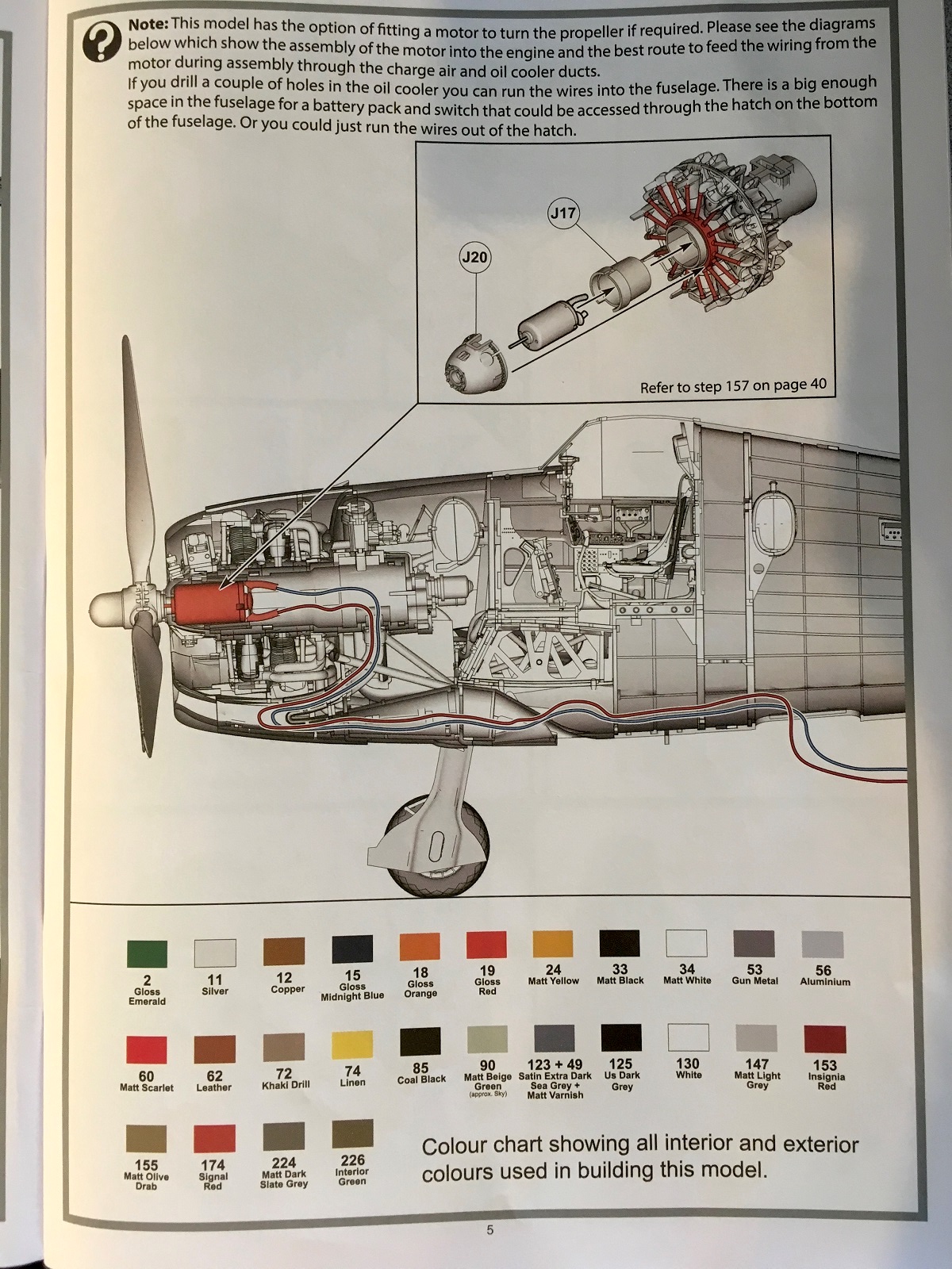
Airfix provides a table of colors that I photocopied and taped near my desk for quick reference. Only Humbrol colors are shown. I used the equivalent in Model Master Enamels and Tamiya paints.
As with all previous Airfix 1/24 scale kits, the modeler has the option of adding a separately available electric motor to turn the propeller. I already had one and used it in this build. Airfix included a detailed cut away illustration showing their suggested route to run the electric wires from the motor to a hatch in the belly behind the cockpit.
Before starting this model, I determined that I wanted to capitalize on the options offered. I wanted one wing folded with flaps up, and the other wing extended with flaps down and gun bays open. While the wings could be folded and unfolded manually (normally hydraulically), I am well aware that the flaps work in unison on both wings. This is my disclaimer on displaying the model in an “unnatural” way! Let’s see what grief I get from this decision, especially at a contest!!!
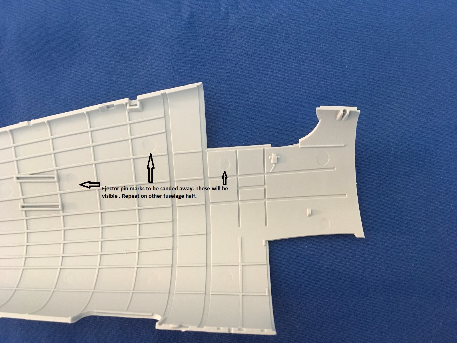
Committing the radical act of following the instructions, I started building the cockpit. I assembled as much as I could that would be interior green. From references, I understand the interior fuselage of late model F6F-5’s behind the cockpit were painted yellow zinc chromate instead of the suggested interior green. The fit of all components was quite good. There were some ejector pin marks that needed to be removed, especially one on either side of the rear cockpit walls as well as a couple in the rear fuselage. These were large but easy to sand away. Two in the sides of the seat were filled with putty. All parts need mold seams scraped and sanded to clean them up. None of this was bad but is necessary for a good clean fit.
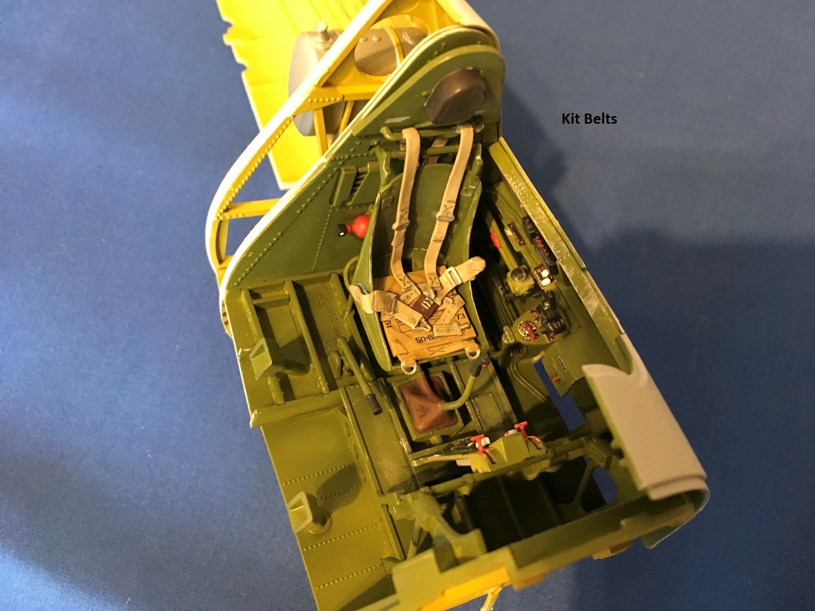
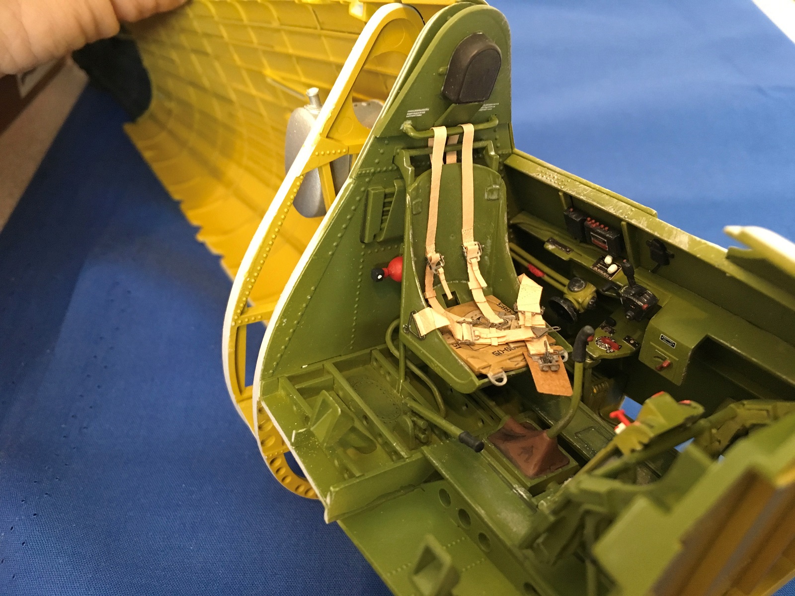
The cockpit is very well detailed, including some electrical wiring, plumbing, and structural parts. After painting and applying the kit-supplied stencil and instrument decals, the large cockpit looked fantastic.
I started this model with the intentions of building it completely out of the box, but RB-Productions sent a set of 1/24 USAF/USN Seatbelts to the IPMS for review so I requested them. The kit plastic seat belts were absolutely fine, and I had already painted, weathered, and installed them on the seat. The kit belts were a little simple but looked good with a bit of work and paint. The RB belts replaced the kit belts, are stunning, and really compliment the great cockpit.
The first issue I ran into was fitting bulkhead (E28) just behind the rear cockpit bulkhead. It seemed to fit in its slot fine but closing the fuselage left a gap of about a 1/8th inch. I ended up sanding the sides of this and the rear cockpit bulkhead, but I still had a small gap that I filled with super glue. I couldn’t figure out why it didn’t fit, other that it being a bit wide? All other fuselage bulkheads fit fine.
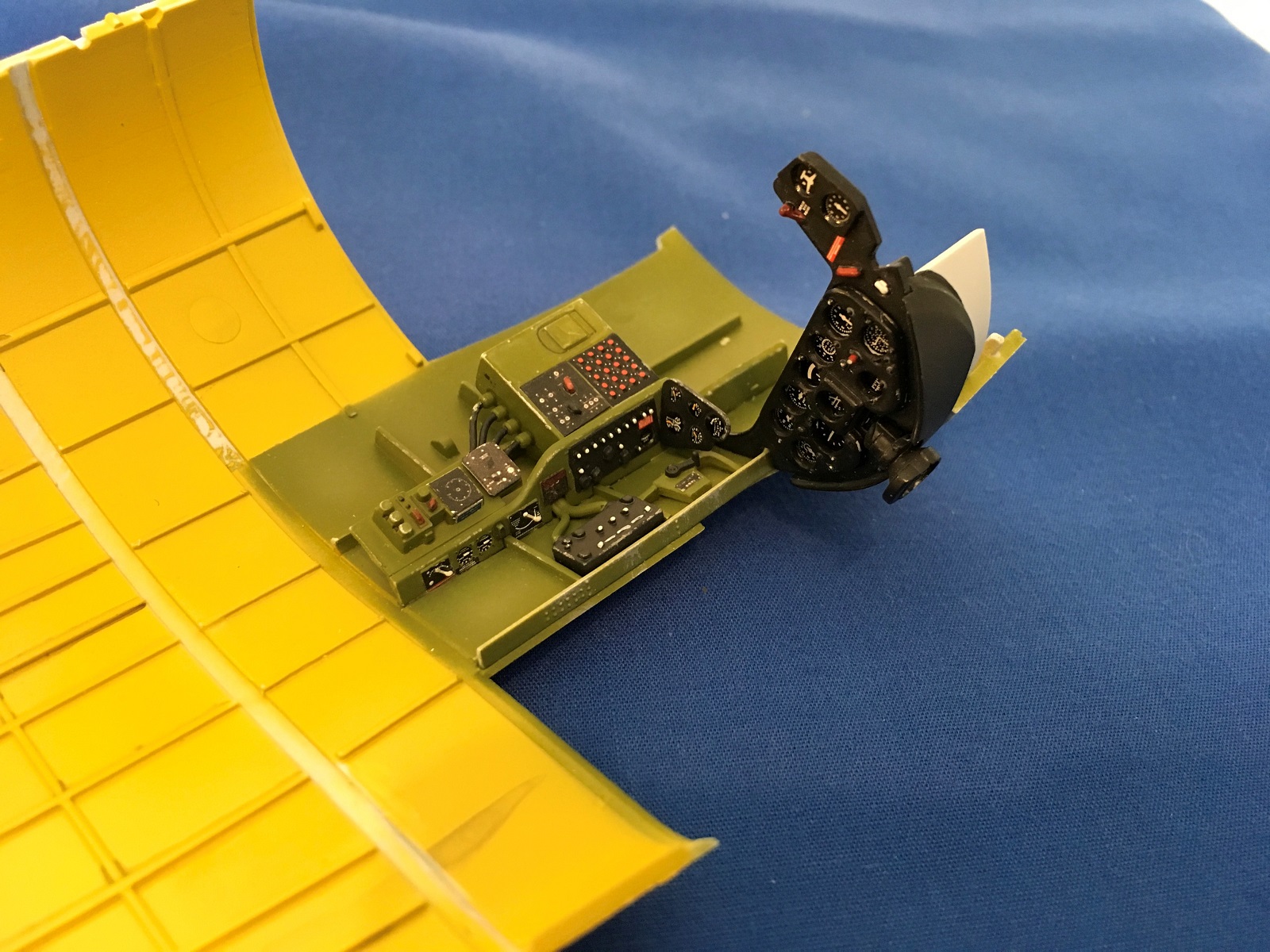
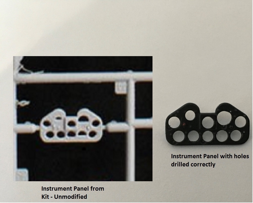
While grouping parts to be painted, I noticed the instrument panel (part E44) had misshaped instrument holes. One was a semi-circle and others looked more like oblong shapes that were not formed properly, in what I could only guess was in the molding process. I have also seen this in other online reviews and build forums. I used a cylindrical file and Exacto blade to form the correct round holes. I measured the size of each hole using the actual decal instrument as a template. See the before and after pictures.
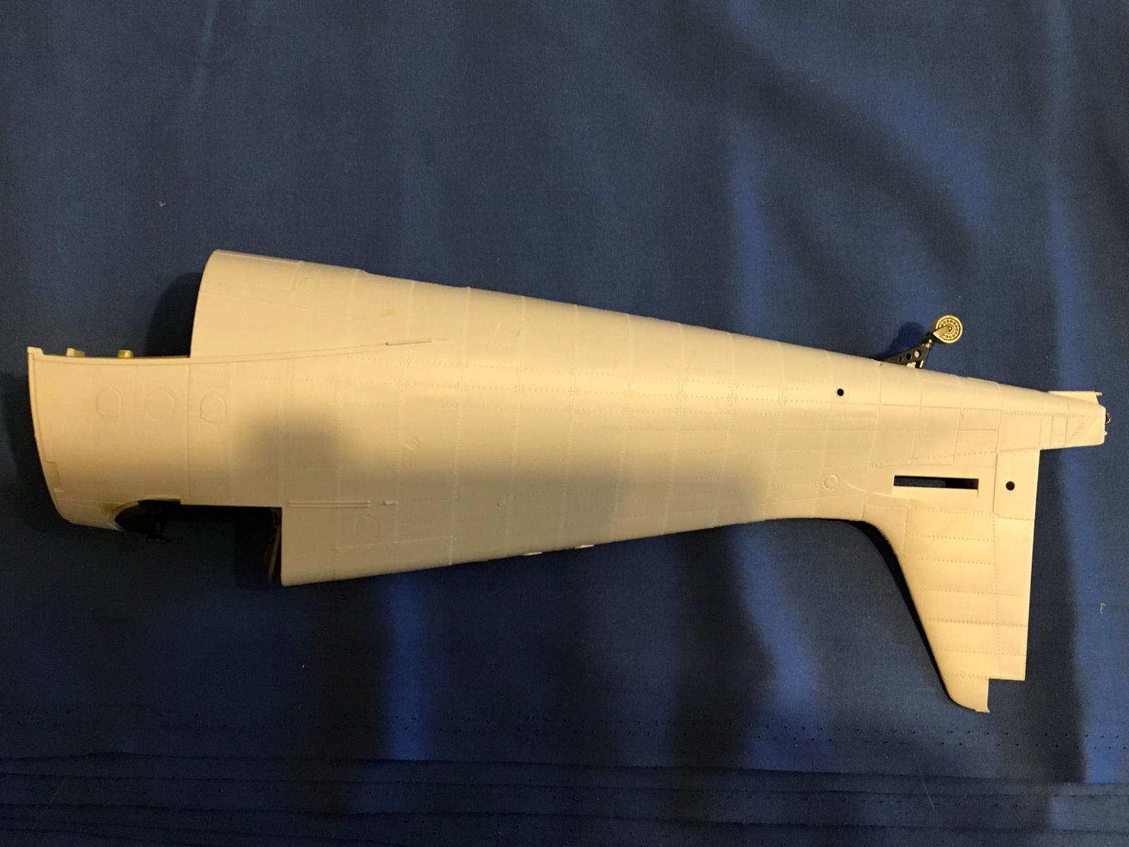
The fuselage haves were glued together trapping the finished cockpit, bulkheads, radio racks, workable tail arrestor hook, and tail wheel. Care is needed to align all the internal bulkheads and racks. The tail wheel can be mounted later, but the fit is tight and easier to attach now.
I ignored steps 44 to 51 as these pertain to building the aircraft in flight with the wheels up. However, in step 46 the main wheels are assembled for all versions. The hubs look great, but the tires could have better crosshatch tread detail. After joining the two tire halves together and dealing with the seam, I used my razor saw to reinstate the lost or soft tread pattern.
The center wing section was assembled next and consisted of inboard wing spars, structural items of the main undercarriage bays, and wing fold assembly. Inboard flap actuators need to be attached. Make sure the correct ones are used for flaps “up” or ‘down”. Everything fit fine.
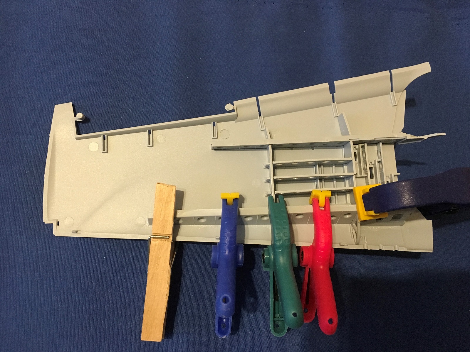
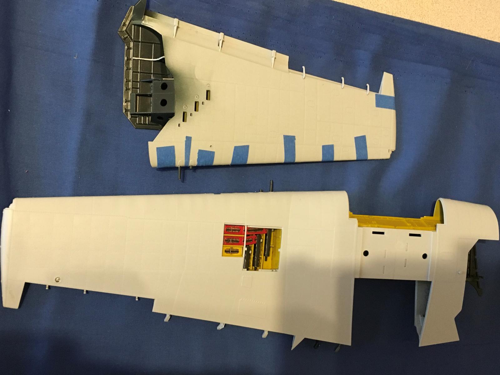
Outer/folding wing assembly begins with gun bays, forward and rear wing spars, bulkheads, and other structural parts being glued to the lower wing. The fit was extremely tight in places and I used clamps to make sure everything was seated where it needed to be. Construction continues with building parts of the wing fold mechanism. The guns and ammo containers need to be added before the wing top is attached and show very nice detail. Care is needed removing and sanding large sprue attachments from the separate gun barrel ends as they are very close to the front. I was a little careless and sanded some of the nice muzzle ends flat. It would have been better to have sprue attachments that are not visible at the rear of these barrel ends.
The wings tops (full left wing and inboard right wing) were glued to the center wing section, followed by the wing bottoms. The folded right wing was left separate. The fit was very tight and I had to sand some internal structures to get a better fit.
The completed wing bottoms attach to the center wing section using substantial wing fold hinges that insert inside the hollow forward wing spars. They were supplied for either extended or folded wings. They were so tight I sanded them until I could slide them in without the risk of breaking anything. She’s starting to look like a Hellcat!!!
The 1/24 scale Airfix Hellcat F6F-5 is a fantastic model with outstanding detail straight from the box. It is by no means a “throw together, “shake n’ bake” kit. A good deal of thought, preparation, and test fitting is needed to ensure a good result. I’m having a blast with this one and I’d recommend it to intermediate and experienced modelers. She’s big, but with one or both wings folded this Cat won’t take up too much shelf space.


Comments
I am building this kit right…
I am building this kit right now. The online build can be found at:
Airfix 1/24 F6F Hellcat | scottmurphyphoto
Add new comment
This site is protected by reCAPTCHA and the Google Privacy Policy and Terms of Service apply.
Similar Reviews