
F-4J Phantom - Base Kit Construction, Part 1
Brief History (Exerpts from Wikipedia)
The McDonnell Douglas F-4 Phantom II is a two-seat, twin engine, all-weather, long-range supersconic jet fighter-bomber and interceptor originally developed for the United States Navy by McDonald Aircraft. It first entered service in 1960 with the Navy. Proving highly adaptable, it was also adopted by the United States Marine Corps and the United States Air Force, and by the mid-1960s had become a major part of their air arms.
The Phantom is a large fighter with a top speed of over Mach 2.2. It can carry more than 18,000 pounds of weapons on nine external hardpoints, including air-to-air missiles,air-to-ground missiles, and various bombs. The F-4, like other interceptors of its time, was initially designed without an internal cannon. Later models incorporated an M16 Vulcan rotary cannon. Beginning in 1959, it set 15 world records for in-flight performance, including an absolute speed record and an absolute altitude record.
The F-4J was a variant for the United States Navy and Marines.
The Kit
There have been a number of positive reviews for the Zoukei Mura F-4 Phantom series of model kits, and I cannot add anything new, other than these are really great kits. This was a most enjoyable project. I would encourage anyone interested in the F-4 Phantom to purchase any Zoukei Mura Phantom. You will not be sorry.
Parts are molded in a medium grey with sprues alpha identified and parts numerically, and are molded clean and chrisp with no flash that I coud see. Vey nicely detailed. The parts radiate quality.
The Instruction Manual
On the surface the kit's instruction manual is one of the most complicated and complete I have ever worked with. However, as with any new kit, the modeler should take the time to review the instructions and become familiar with the steps. This manual is very thorough and will lead the builder through the process of assembly to avoid fit issues. There is some back-and-forth for some of the steps. Just pay attention. Page 30 shows the modifications required to build the model in a catapult launch configuration. If the modeler choses to go this route you will need to outsource crew figures for the cockpit as none are included here.
Page 31 of the instruction manual depicts the parts list, identifying parts not to be used in this build.
Clear Parts
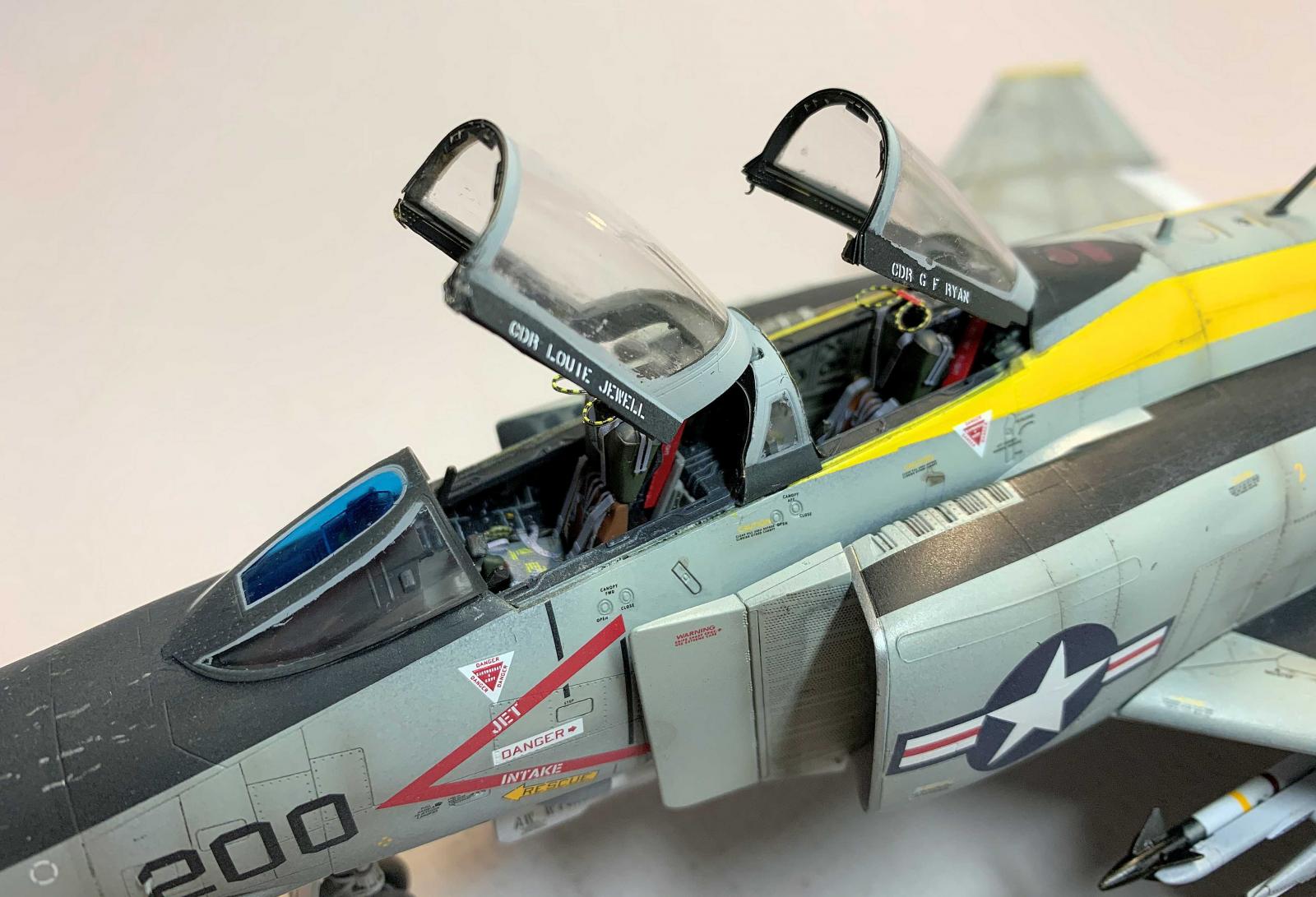
The Zoukei Mura F-4J kit clear parts come on a single sprue and include a separate closed canopy, four parts for an open canopy option, a top-of-fuselage position light lens, gun sight, a vertical stabilizer anti-collision light plus some small miscellaneous lenses. The canopy clear parts appeared a bit hazy and looked like some very fine marring was present on all of the parts. I carefully removed the open canopy parts from the sprue, and cleaned up the attachment points.I used Novus plastic polish to buff out any defects, rinsed the parts with glass cleaner, and when dry dipped the parts in Future. I set the parts aside to cure for 48 hours.
Decals/Marking
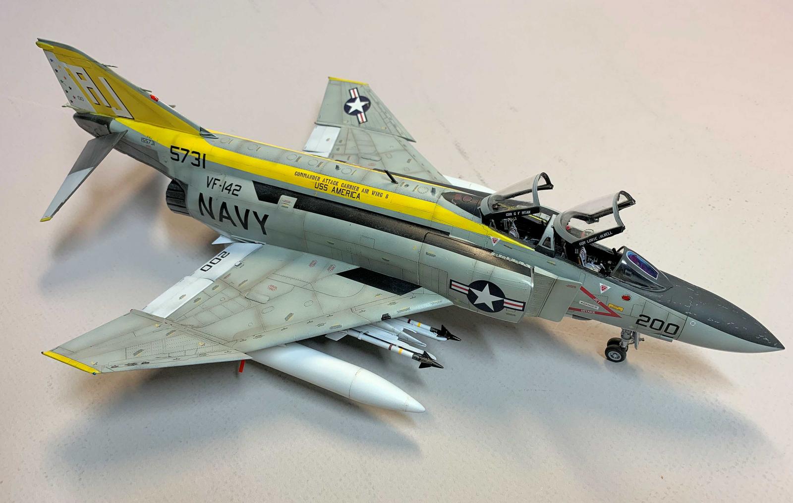
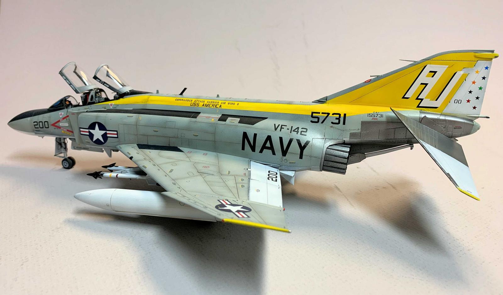
One large decals sheet is included with markings for one aircraft, Bu, no. 155731 VF-142 USS America 1974. A large, glossy, two-sided location information sheet in also provided. This was very usefull when placing the various markings and stencils included on the decal sheet. In addition, paint colors are noted, based on Vallejo Model Air and Model Color. The locations for decals are numbered as are paints required for various surfaces and details.
Aftemarket Accessories Used
Several months ago I had the opportunity to review the following Hypersonic Models aftermarket accessories that I had originally planned to use on a Zoukei Mura F-4S Phantom. However with the recent opportunity to build and review the "J" version I decided now is the time to utilize these accessories. I will address my efforts on describing the modifications to the kit with the inclusion of the following accessories into the build in separate reviews.
- Part 2 Hypersonic Models HMR 48016-3 F-4 Phantom Canopy Details
- Part 3 Hypersonic Models HMR 48032 F-4 Phantom Stabilator Upgrade Set
- New Ware Masks NWAM0332 F-4J/S Phantom II Canopy Expert Kabuki Masks (included in Part 1).
- New Ware Masks NWAM0333 F-4J/S Phantom II Exhaust Nozzles Kabuki Masks (included in Part 1).
Construction
Cockpit
I started with the ejection seats. Each seat is built up from five parts. There were five line drawings showing the fit of each part with paint colors called out as well as cementing positions. Each part is also called out by name (survival kit, lumbar pad, etc.). This is a nice information feature and sets the format for the rest of the assemblies I painted each part separately before assembly. The kit did not include seat belts. I used a photoetch set by Eduard. The face curtain pull handles are a separate part and I planned to replace the handles with PE so I cut the handles from the plastic part before adding the remainder to the top of each seat.
Although I normally prefer to use PE for the instrument panels but here I decided to use the cockpit decals for the side consols and instrument panels. The individual decals laid down over each location and with a bit of Solvaset settled down over the irregular surfaces. I used the end of a cotton Q-tip to encourage each decal to conform to the panels. Once settled and dry I airbrushed a clear flat finish over the cockpit to seal everything in place. The application looked quite convincing.
The cockpit and nose gear well are created from the same parts. The cockpit floor surface (Part C28) has several ejector pin marks but many are eventually concealed by other parts of the cockpit assembly.
Main Gear Wheel Wells
The wheel well side walls are two parts that are glued to the bottom half of the wing and then sandwiched by the top wing. The landing gears struts are fixed in place later in the construction which is nice as any early installation of these parts can result in broken parts. There are slots at the outboard side of the main gear wells that except tabs on the main gear. This provides a solid fit.
Fuselage Assembly
The lower fuselage is molded integral with the inboard wings section. Step 13 on page 11 show how to open holes in the bottom surface if the wing tanks and missille pylons are to be mounted. The sizes of the holes are noted in millimeters. There are also references to other pages and steps to clarify what work and parts are required in the future.
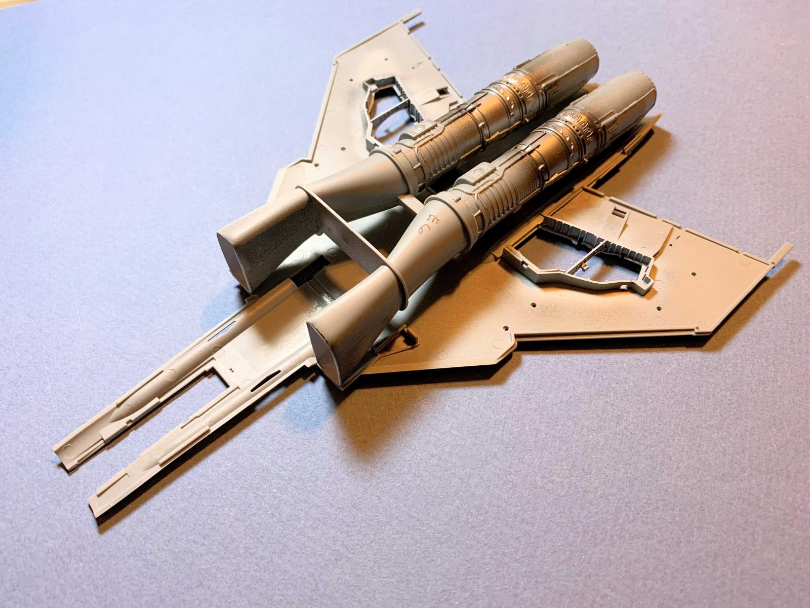
The intake trunks are made from two parts, a top and bottom. Although the fit is very good there will be visible seams on either side of each intake due to the slightly rounded surface of the mating edges. After gluing the parts together I allowed the solvent to set over night. The seam was filled with acrylic putty and allowed to cure before sanding. The intakes and engines were glued together and once the solvent had cured the assembly was fitted to the bottom of the fuselage. There are four locators in the bottom of the fuselage that will align with the intake-engine subassembly. Great fit for these parts.
Fitting the cockpit to the right side of the upper fuselage is shown on page 7 of the instructions. This page also includes a caution note to align the cockpit properly before fitting the two upper fuselage halves together. The right side of the upper fuselage has two alignment rails that help with this step, but once the cockpit is in place the forward rail is almost hidden from view. There are at least three areas that require coordination to align properly: the rear cockpit bulkhead, the front portion of the nose gear wheel well, and the side rail that fits to the fuselage side. It required a bit of effort before the parts were properly aligned and the solvent applied. The left side was fitted in place, taped to hold the parts together, then the solvent could be applied. It's starting to look like a Phantom.
Step number 20 addresses the installation of the engine air intakes. There is a sub note that I overlooked requiring the removal of some raised detail on both intakes. I noticed this after the painting was complete and too late for removal. As noted prviously the instructions are complication so paying attention is a must.
Nose weight was added to the separate radome. Several lead sinkers were placed in the cavity and glued in place.
Stabilators Upgrade
Refer to Part 3 of this review for the detailing of the stabilators with the Hypersonic Models upgrade.
Wings
Follow the instructions and these parts will all fit nicely. Make sure to drill all openings before assembly as noted in the instructions.
Landing Gear and Wheels
These items were assembled per the instructions and installed once the model had been painted and decals applied. I needed to trim part of the main gear mounting tabs to fit into the outboard mounting slots. The slot is a bit hidden from sight and took some fiddling to get things to fit.
Canopy Painting
New Ware Masks
These masks are Kabuki type material with masks for the interior, exterior with masking to permit the painting of the exterior canopy sealant. Multi steps effort but worth it in the end.
Refer to Part 2 of this review for the detailing of the canopy with the Hypersonic Models upgrade.
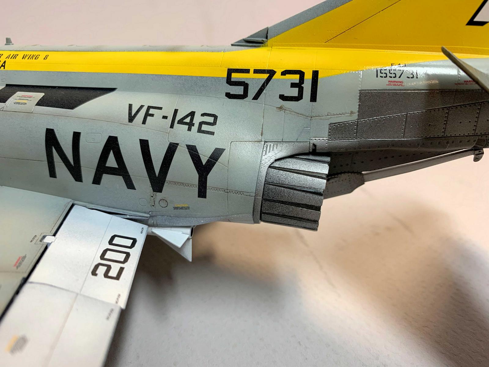
Exhausts Painting
New Ware Masks
These masks are Kabuki type material with masks for the exterior sufaces for the interior petals on the Phantom exhausts. Several spare masks are included (enough for a second Phantom!). This is a simple mask set comprised of sliver-like masking strips. Although the work may be tedious, the end result is well worth the effort.
Exhausts
I first painted the exhaust nozzles with Alclad Black Primer, followed by various Alclad metallics. Installatio was held off until the model had been painted. The finished nozzles fit in the fuselage rear with absolutely no issues..
Painting
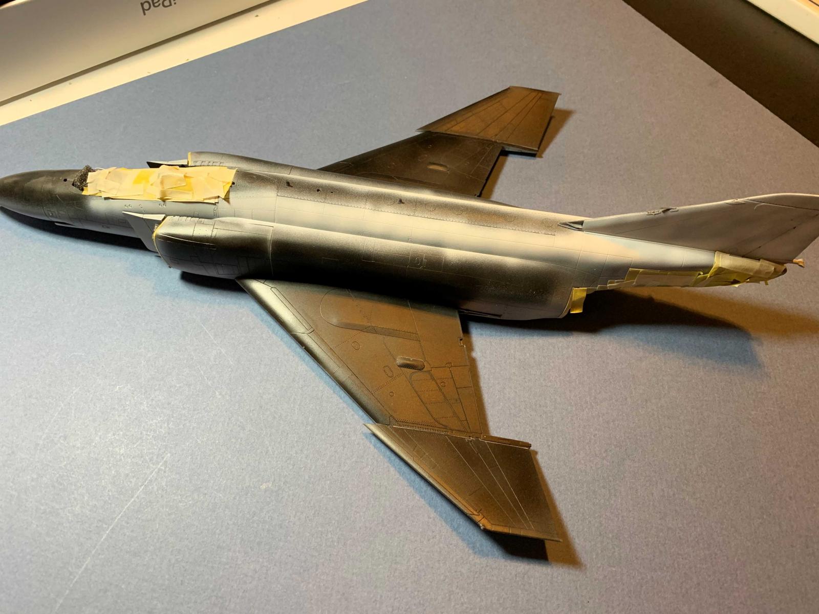
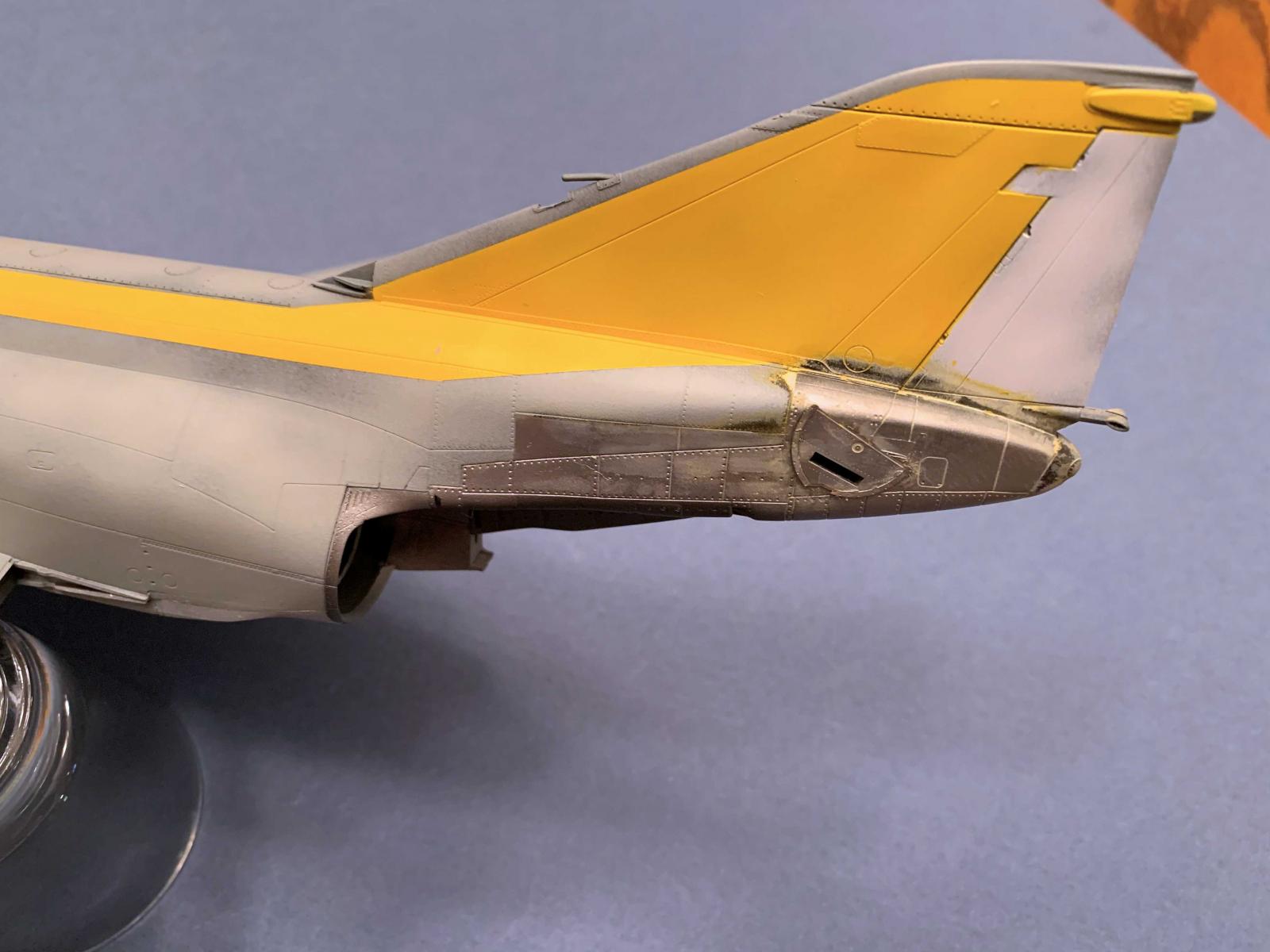
The model was primed with Alclad black primer and allowed to dry for two days. The undersides were airbrushed with Tamiya white surface primer thinned with Mr Color self-leveling lacquer thinner. When this had thoroughly cured I airbrushed Model Master gloss acryl over the white and let that cure. I was really struck by the fine panel lines and detail on this model. A panel line wash will add to the appearance.
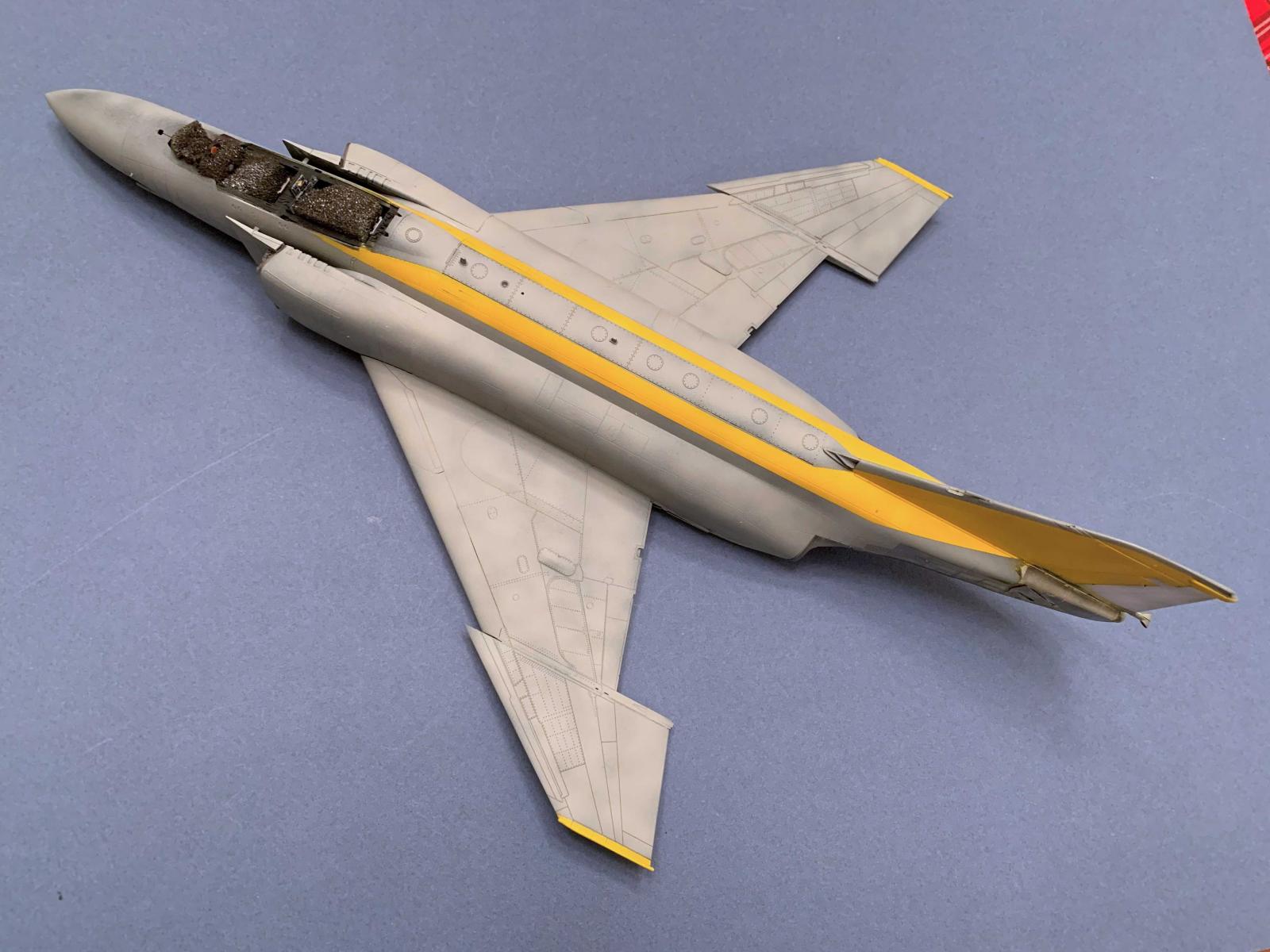
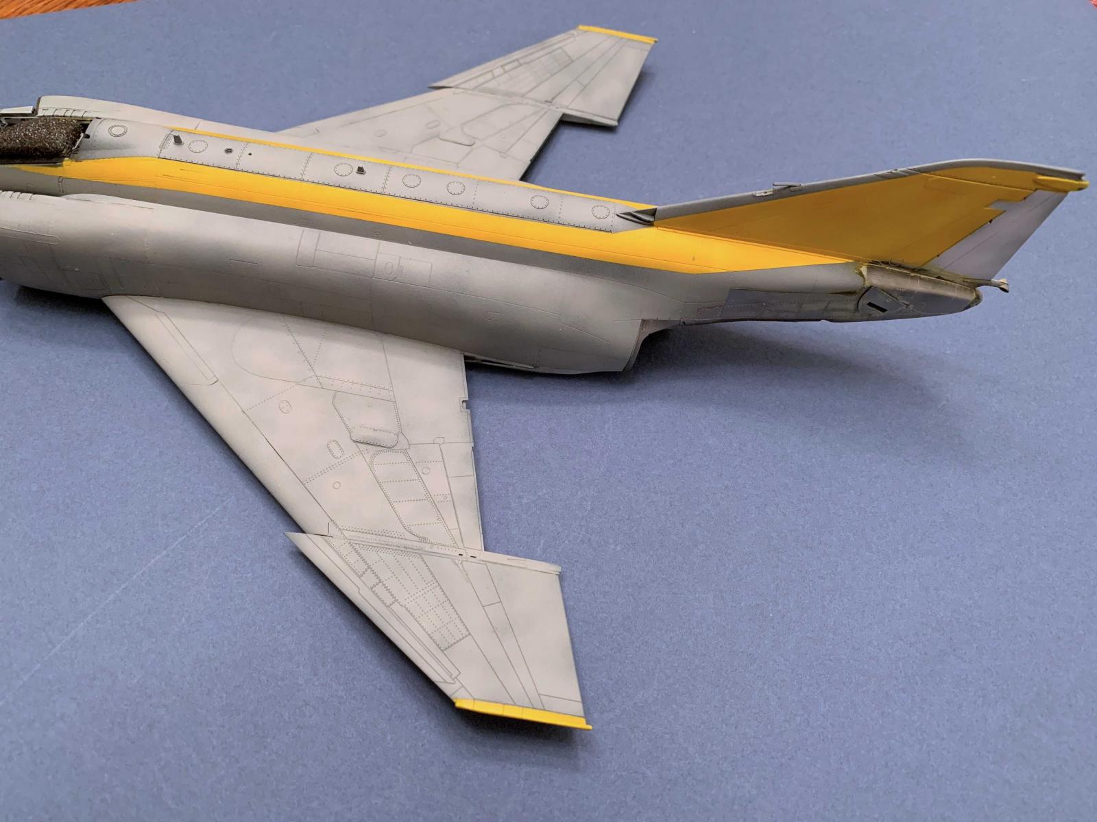
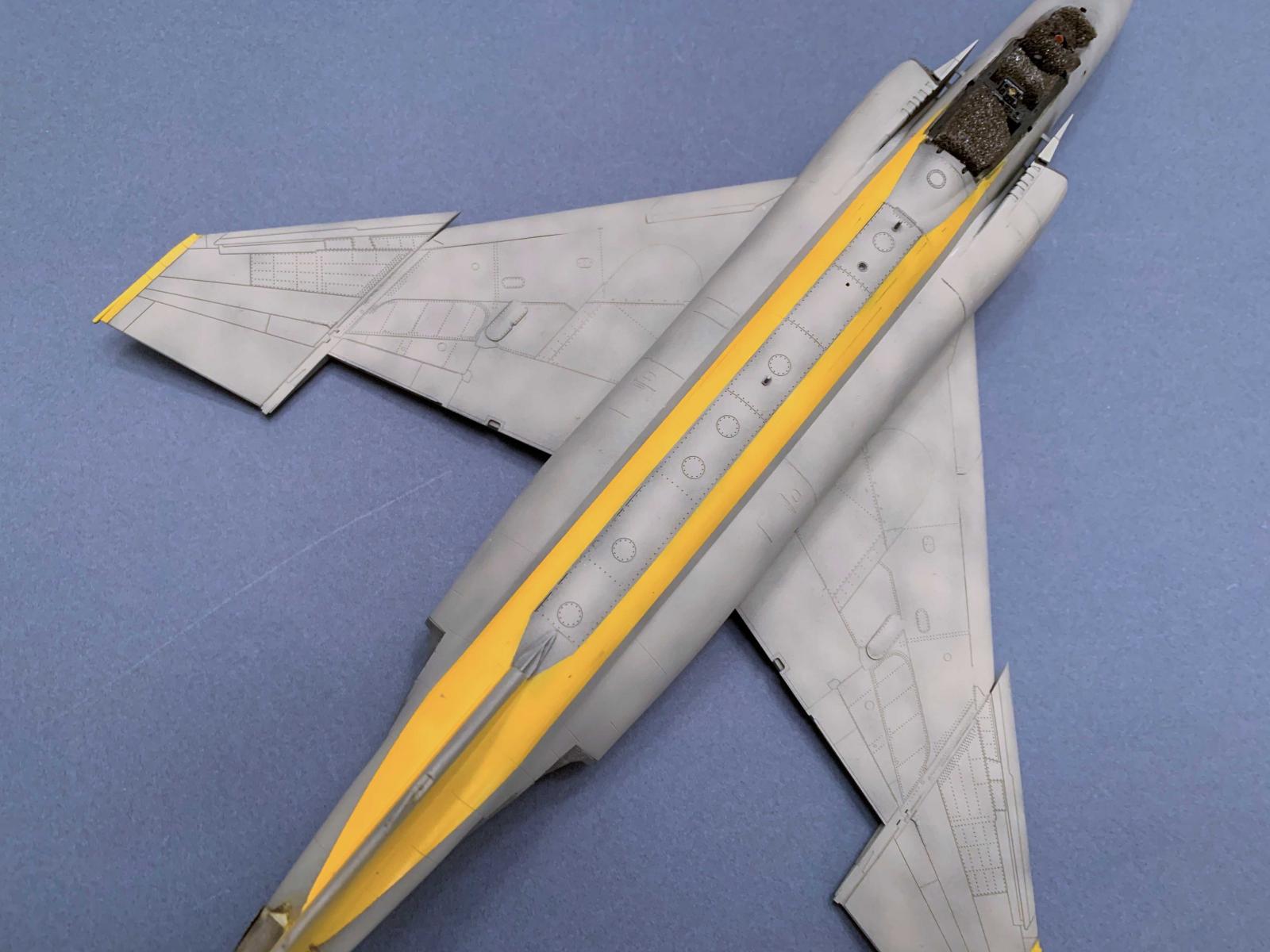
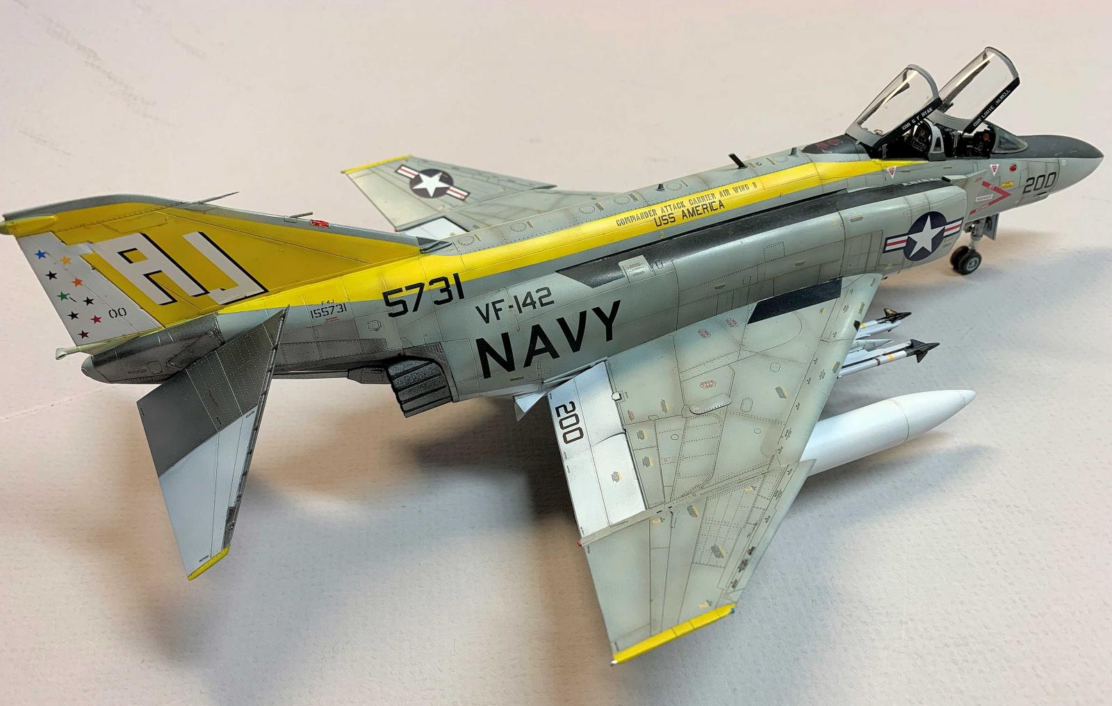
Since the kit was furnished with markings for one Navy aircraft that sported a yellow tail, wing tips, tips of the stabilizers and longitudinal panels down the fuselage I needed to paint those areas white before the yellow was applied. Again I used the Tamiya white surface primer. Tamiya Flat Yellow was next used here. Once dry the yellow was masked, Alclad black primer was used to touch up the yellow overspray. I followed the kit's painting recommendations and used Vallejo Model Air FS 36440 Gull Grey, thinned with Vallejo Airbrush Thinner. This was the first time I airbrushed Vallejo Model Air paints and I was really impressed with this paint.
After removing all the masking I found I had various small spots of paint creep in several areas. I used sellective masking and touched those areas up with the appropriate colors.
Decal Application
Once the painting and touch-up painting had been completed on the model I applied three thin coats of Model Master Acryl Gloss and allowed that to cure for 48 hours.
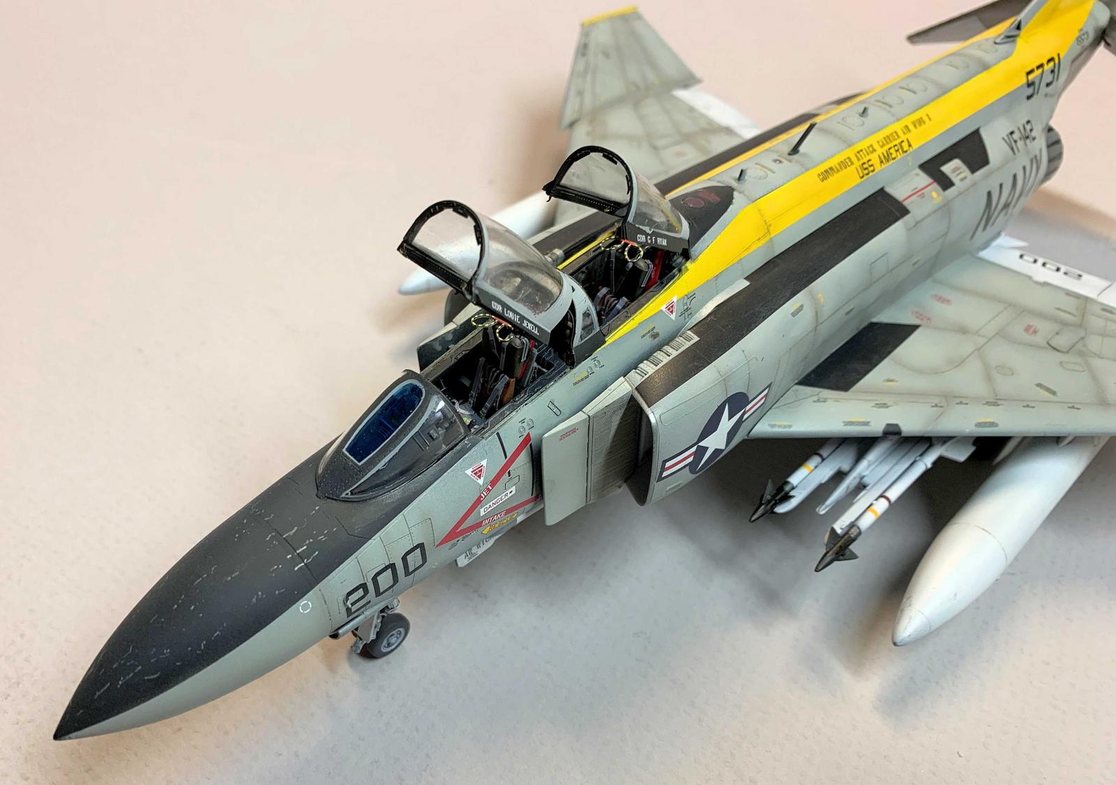
The decals are printed by Cartograph. Plan on severals hours of time to apply the decals. There are at least 80 stencils on the undersides alone. There are decals for the pylons and weapons. Decal 161 is the forward stripes on the Sidewinder and should be cut into two parts to better confirm to the missile body and raised details. Also, decal 165 is mounted on the rear of the forward fins on the Sparrows should be cut the long way and placed individually on the sides of the fins. It took me one or two hour sessions over three days to complete the decals application.
Panel line washes are a modeler's personal choice. Panel line washes were done with Mig PLW Neutral Brown on the undersides and the topsides. The chrisp panel lines and details on this model really stood out with the washes and enhanced the overall appearance of the finished kit. The model was given a final coat of Model Master flat.
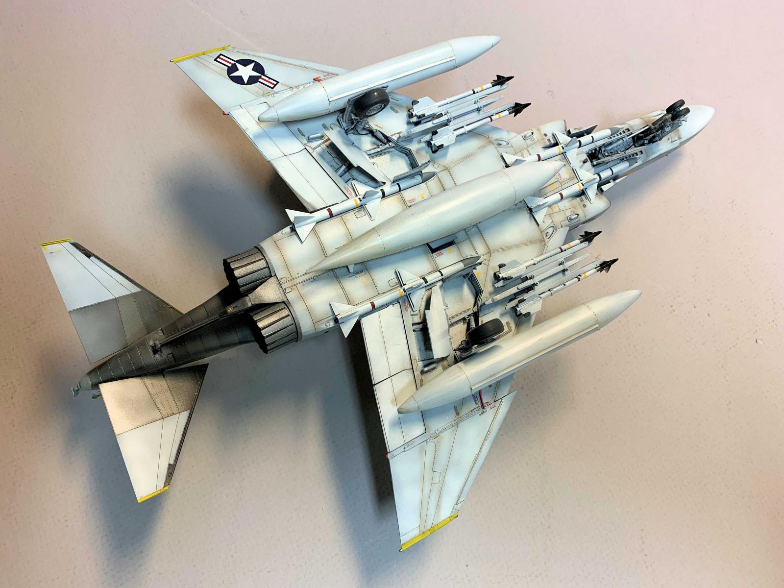
Underwings Stores and weapons
The fuel tanks, missiles and pylons were assembled and painted separately. Once the model had be completed, painted, decals applied and sealed I glued these assemblies in place.
Conclusion
First, this kit is not for the beginner. The instructions are quite complicated and there are many parts, small and smaller, to deal with in the assembly. However, the end result is very rewarding and the model is really amazing. The parts fit is precise for the most part, and the parts are chrisply detailed. Every time I placed one assembly with another I was amazed at the fit. Only one or two minor gaps required filling with acrylic putty. It was superb! No flash on any of the parts. Ejector pins marks were not an issue in this build.
Adding the various Hypersonic upgrades made this build a bit more of a challenge. The inclusion of the HyperSonic resin upgrade accessories is in no way meant to diminish the quality of the Zoukei Mura kit, but is offered to those who wish to add some challenges to their modeling efforts. All the products used are high quality products and designs, and raise the level of detail.
When following the instructions the many line drawing views of the various sub-assemblies will assist the modeler with the fit and orientation of the many parts. The several supplementary diagrams also assure the correct placement and orientation of the parts. Pay attention to the notes!
The instrument panels decals were well planned and worked nicely, eliminating the need for an aftermarket PE set. Seat belts, if desired. must be out-sourced by the modeler.
The vertical stabilizer on the right half of the fuselage is molded with two probes in place. I saw immediately these needed to be protected during the assembly process. I taped two small foam board panels to protect the probes, but after removing the foamboard to complete some final steps in the work I managed to break and lose one of the probes. The lost probe was replaced with brass.
When painting the model as the kit scheme the modeler will be faced with some masking challenges. Checking and following the color profiles provided will assist in this effort and the end result will be stunning.
Zoukei Mura have certainly set the bar for the other kit manufacurers not only in the quality and detail of the plastic in this kit, but also with the format and content of the instructions. I truly enjoyed this build and was almost sorry when the effort was complete. This is truly an amazing kit and the fit and detail is outstanding. This Zoukei Mura kit is highly recommended and will stand on its own merit without aftermarket accessories. I now have to build the S version to compliment this F-4J. This kit should set the standard for other kit manufacturers.
I wish to thank Volks Zoukei Mura and IPMS USA for the opportunity to build and review this kit. This kit is very highly recommended.


Comments
Add new comment
This site is protected by reCAPTCHA and the Google Privacy Policy and Terms of Service apply.
Similar Reviews