
DKM H Class Battleship
Intro
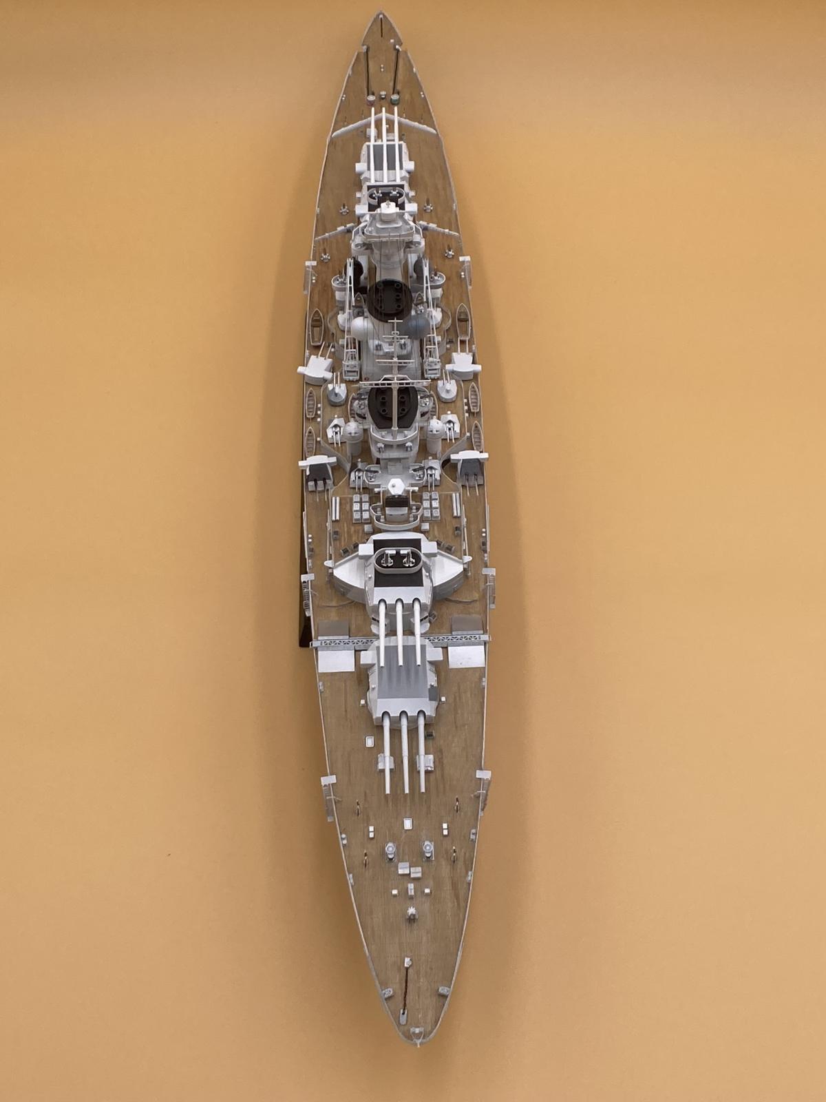
I have to tell you that I bet there will be a couple jealous reviewers out there after they see this ship, wishing they had jumped on the review opportunity! The quality of this kit is really worth it, and it was an exciting ship to build based on the detail level and the overall engineering. Trumpeter has thought through a number of significant elements that make the build feel easier. For instance, thoughtful orientation of sprue gates such that almost no marring occurs on visible surfaces, and error proofing orientation by using 2 different sized alignment pins on parts. You’ll find top-notch photo-etch in the kit, easy to nip off the sprue and not so hardened that it breaks if you bend it the wrong way the first time and have to reverse the bend. Lastly you’ll have to decide if you want to go the H-39 route with the provided twin mount turrets, or the World of Wargaming triple mounts. I chose to build both for the review and display it with the big triples in the box-art paint scheme. Also, given that only the hulls of these ships were originally laid down, it is represented as if it’s just leaving the ship-yard. Lastly, I would recommend a reference for German Battleships to help with details and overall configuration as I’ll highlight in key places of the review.
Hull
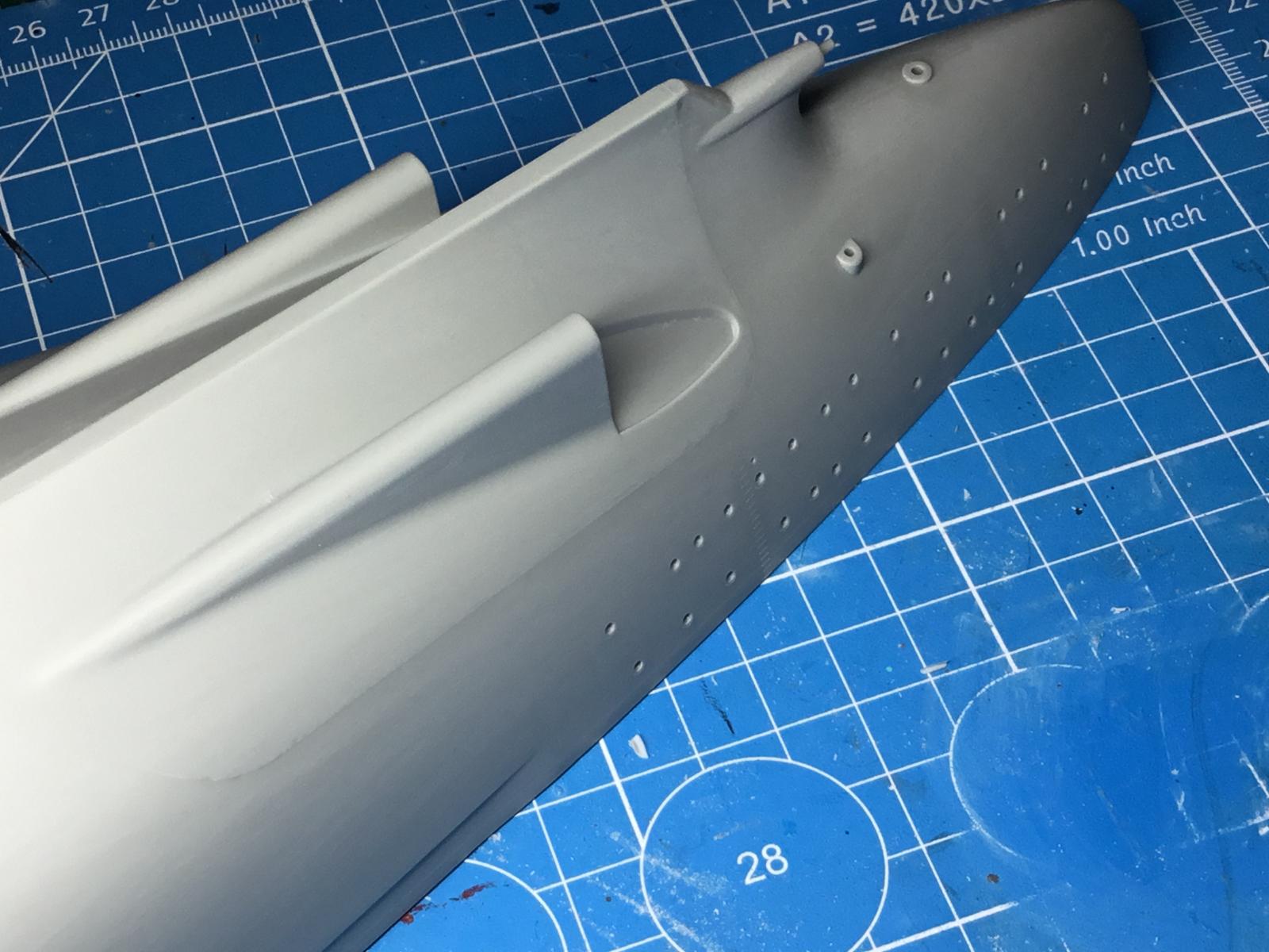
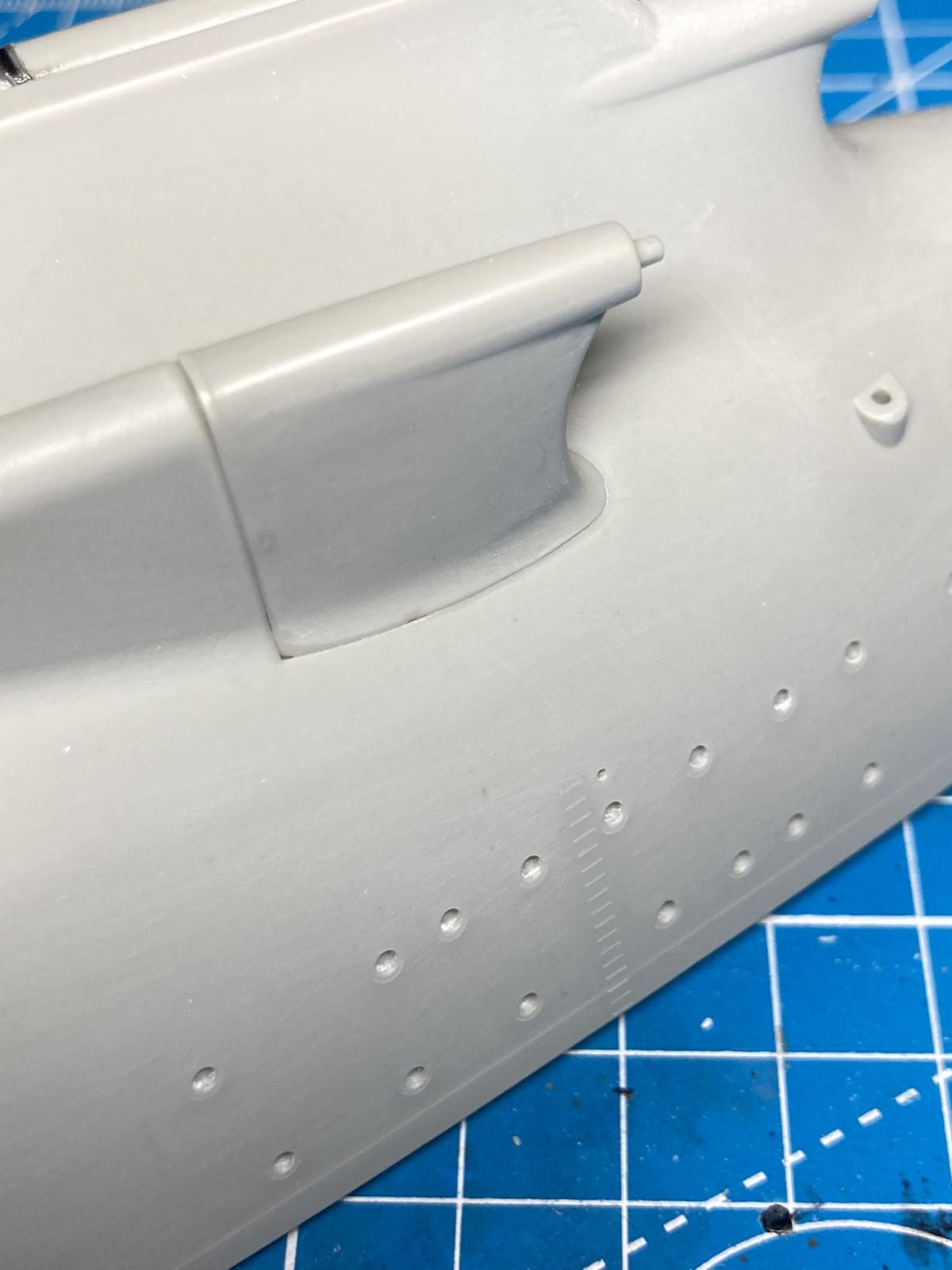
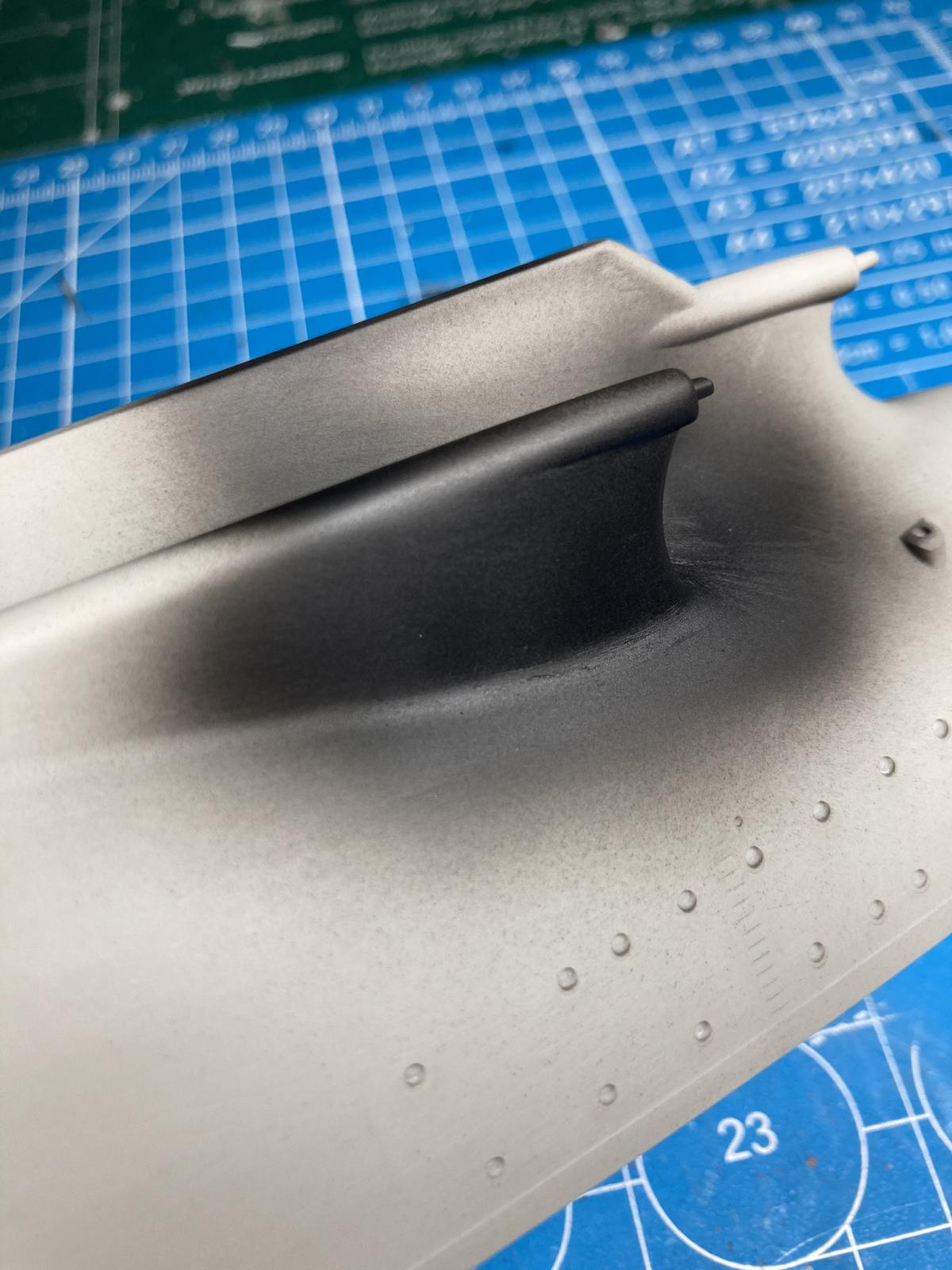
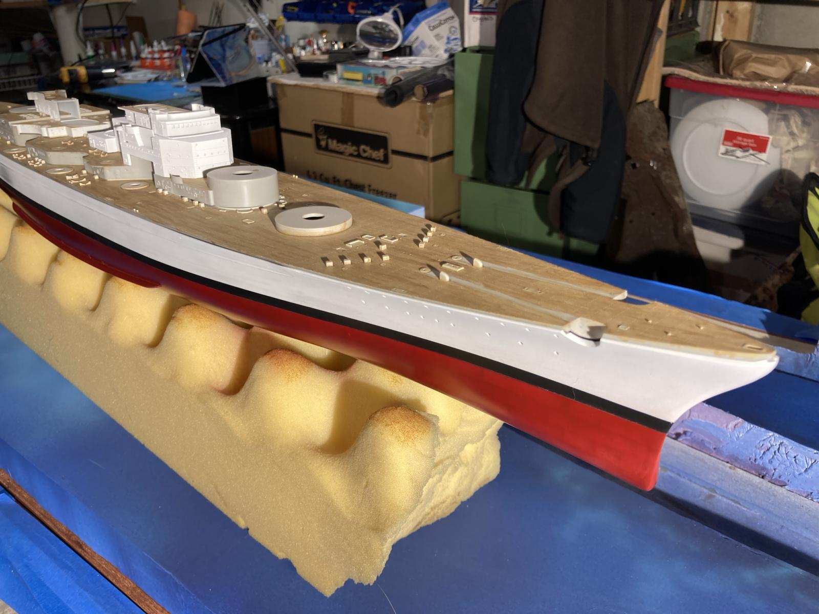
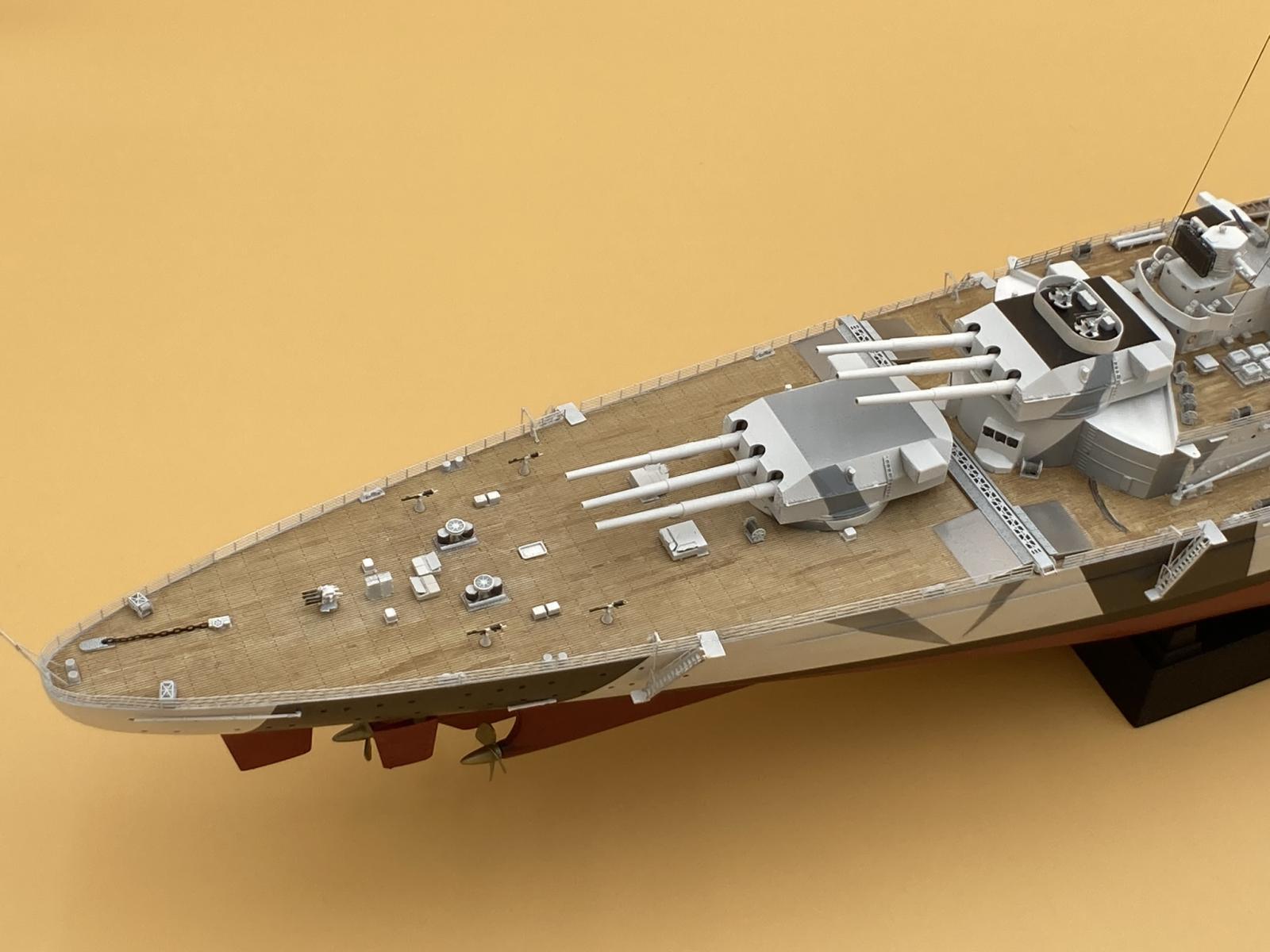
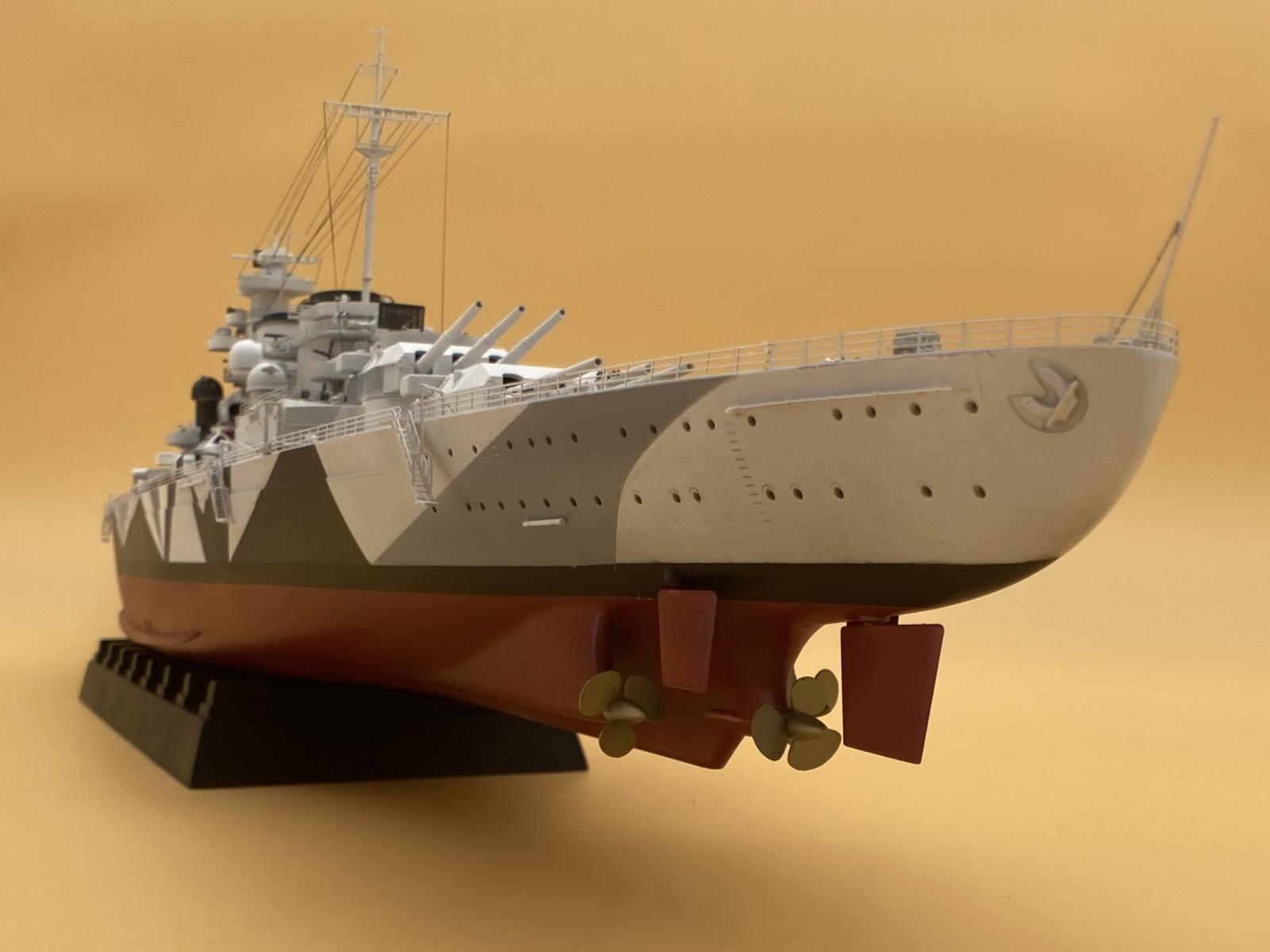
Right off the bat, step 1, let’s change it up. I opted to skip a part of step 1…I’ve run into trouble before gluing in the girders across the hull without fitting the deck at the same time. This can result in gaps at the edge of the deck that have to be filled. Keeping the deck separate so it’s easier to finish works better for me so I just glued the girder pins and left the sides free. Trumpeter throws in AA gun assembly in steps 2-5. I did these in-between assembling, filling, and sanding the 2-part shaft skegs. Also, jump ahead to step 43 and assemble the stabilizers at step 6 as well. If you’re like me and plan to paint the hull before anything else this is a mandatory step, although I just can’t see assembling these the way Trumpeter recommends in any scenario, as it will be hard at step 43 to lay the ship on an angle with the superstructure built up. Trumpeter’s hull form results in reduced sanding and sprue gate issues to clean up along the bottom of the hull, resulting in way less work to display it on an elevated stand (rather than the standard simulated wood blocks and cradles). Though with “the hull made from two-directional slide molds” I didn’t expect the two outer skegs to be assembled and the seams filled and sanded smooth. Plan to spend extra time on this before doing any other hull construction (pics 17-20). I used black CA to get a joint that would disappear under primer. Hold off on the props and rudders until you are done mounting the deck to avoid breaking off parts. I found these easy to install near the very end of the build. Make sure you paint the top of the small, outer, rudders. This shows when installed and so must be painted to match the rest of the rudder. I chose to drill out the portholes at this stage. The recessed markings made it easy to center a drill bit and leave the eyebrow over each porthole. Photo 29 concludes the hull with the deck just set in place and shows how well it can be painted up.
Deck
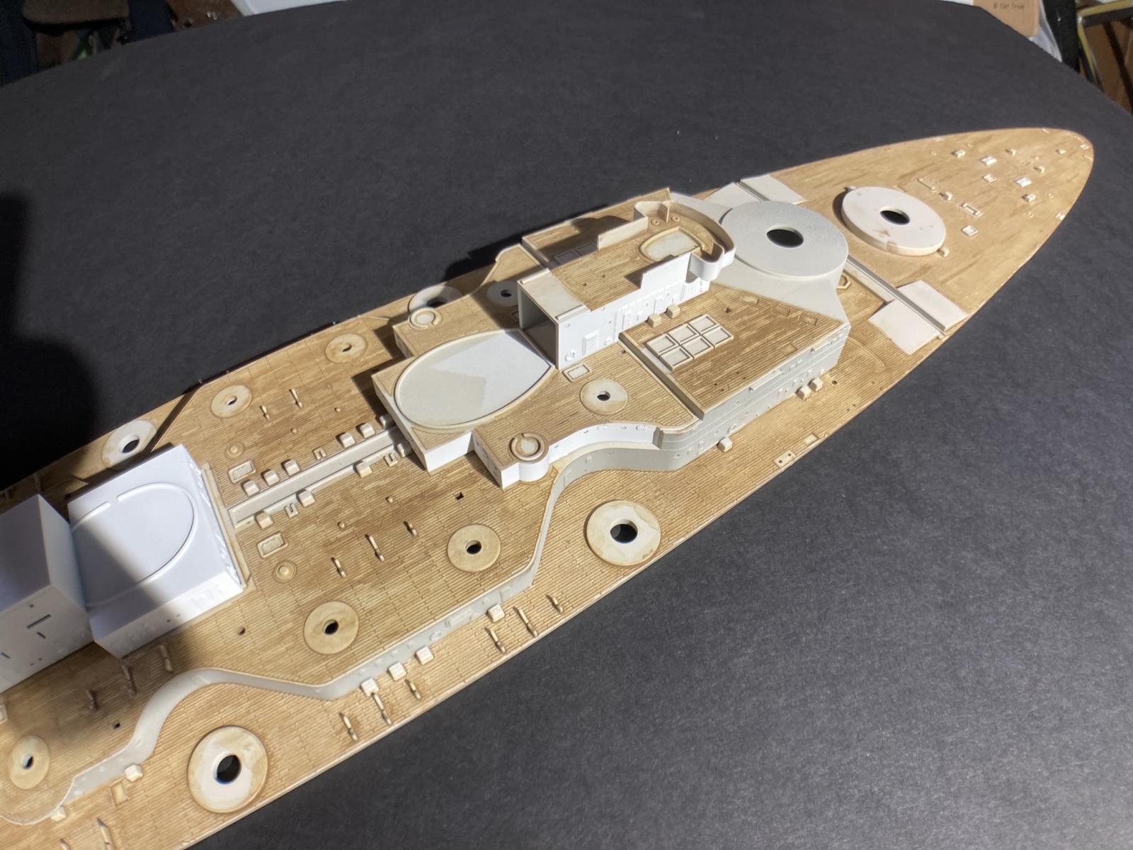
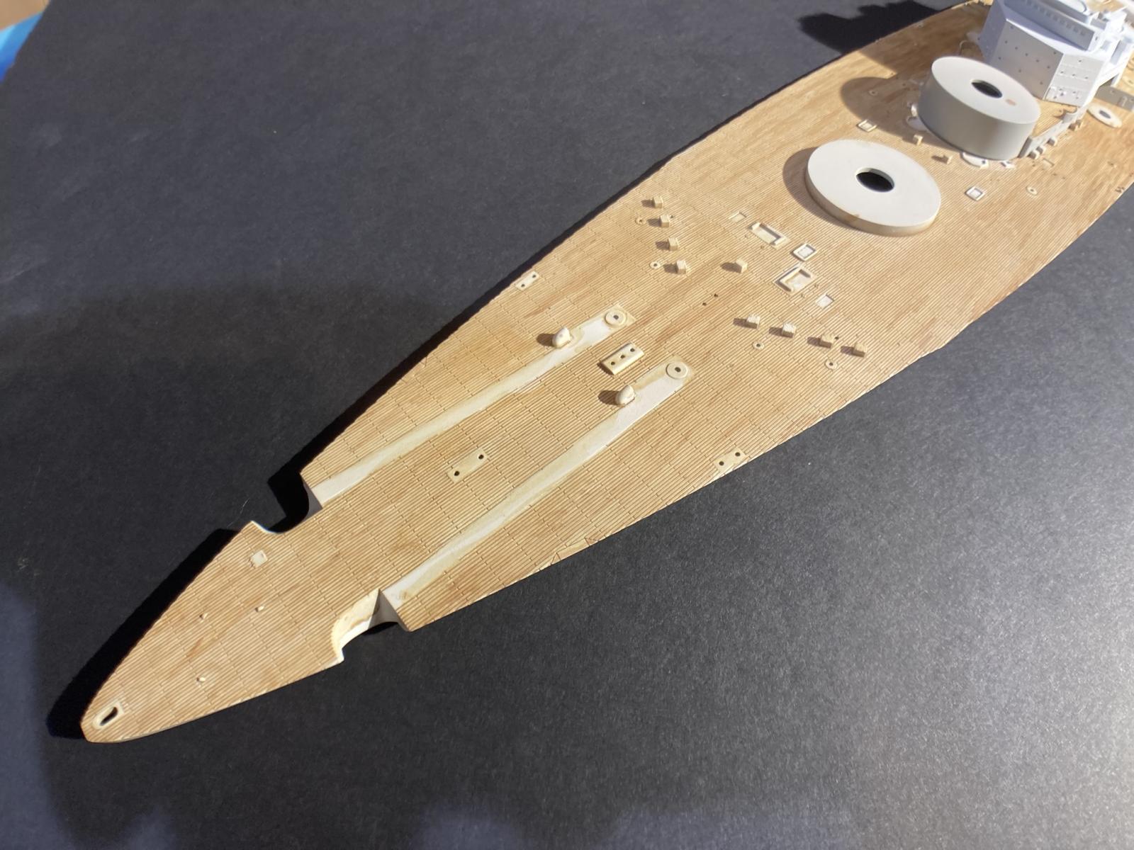
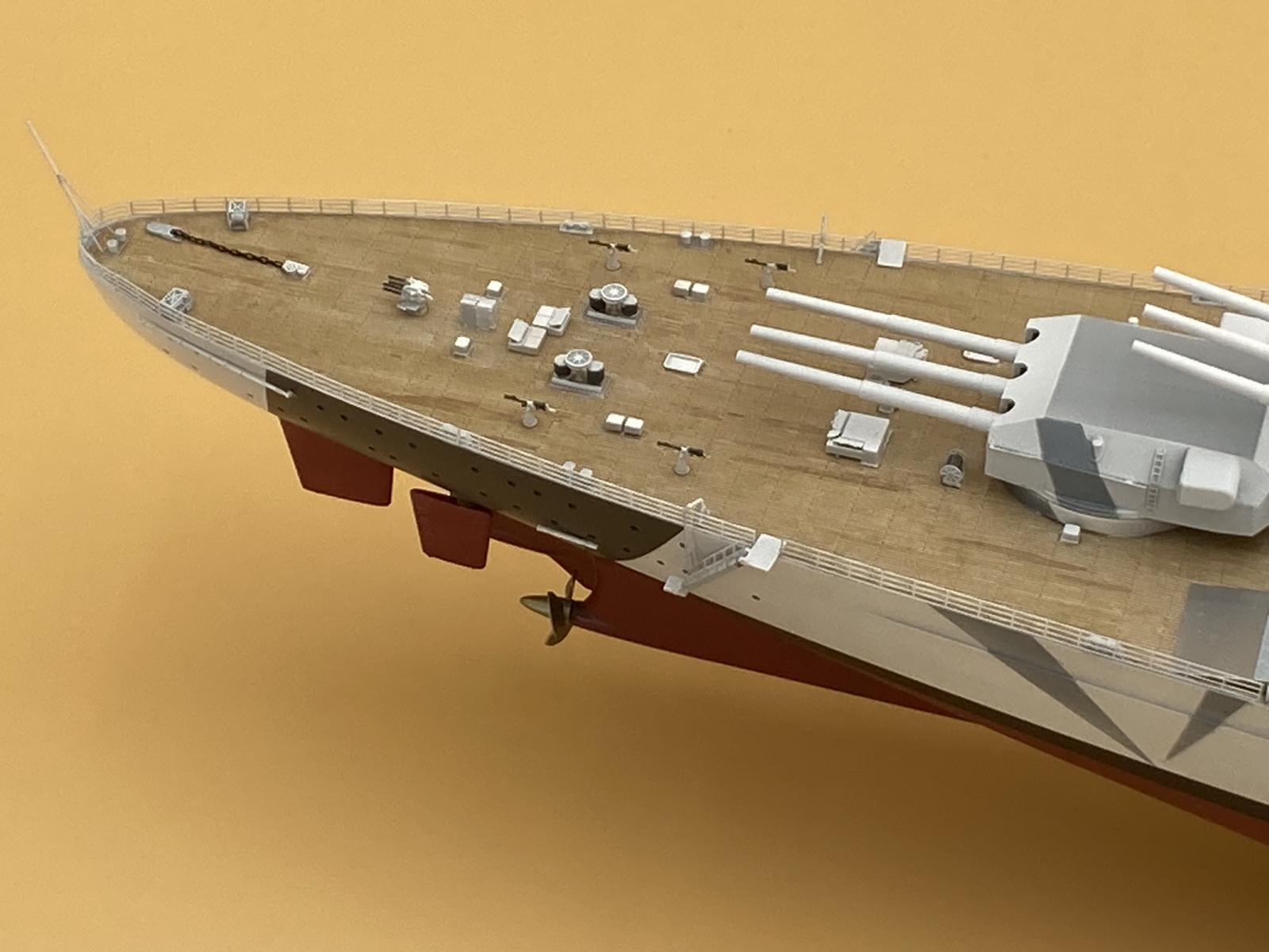
The real benefit of the deck design is really seen near the end of the build as you add the myriad of fittings and details to the deck. Not molding these into the deck gives it a crisp finish and makes painting quicker and cleaner without having to go back and retouch fittings after painting the deck itself. For major pieces like the wave breaks there are no rounded corners where they meet the deck that look unnatural. Although I have to say even the fittings that are molded to the deck have fairly delineated edges. The deck itself has molded wood planks that turn out quite realistic. For this approach I’ve combined techniques from different modeling categories, figures and aircraft, to come up with something unique and relatively easy to do. Using a panel liner, a wash, glazes, and a bunch of micro-brushes a fairly realistic deck surface can be created. Look for a full tutorial in an upcoming IPMS magazine issue.
The final technique goes like this:
- Primer the deck,
- Apply a gloss clear,
- Brush on the panel liner,
- Add and remove panel liner to create individual planks,
- Apply a satin clear,
- Apply multiple goats of glaze,
- Finish with a satin clear for a new deck and stop here.
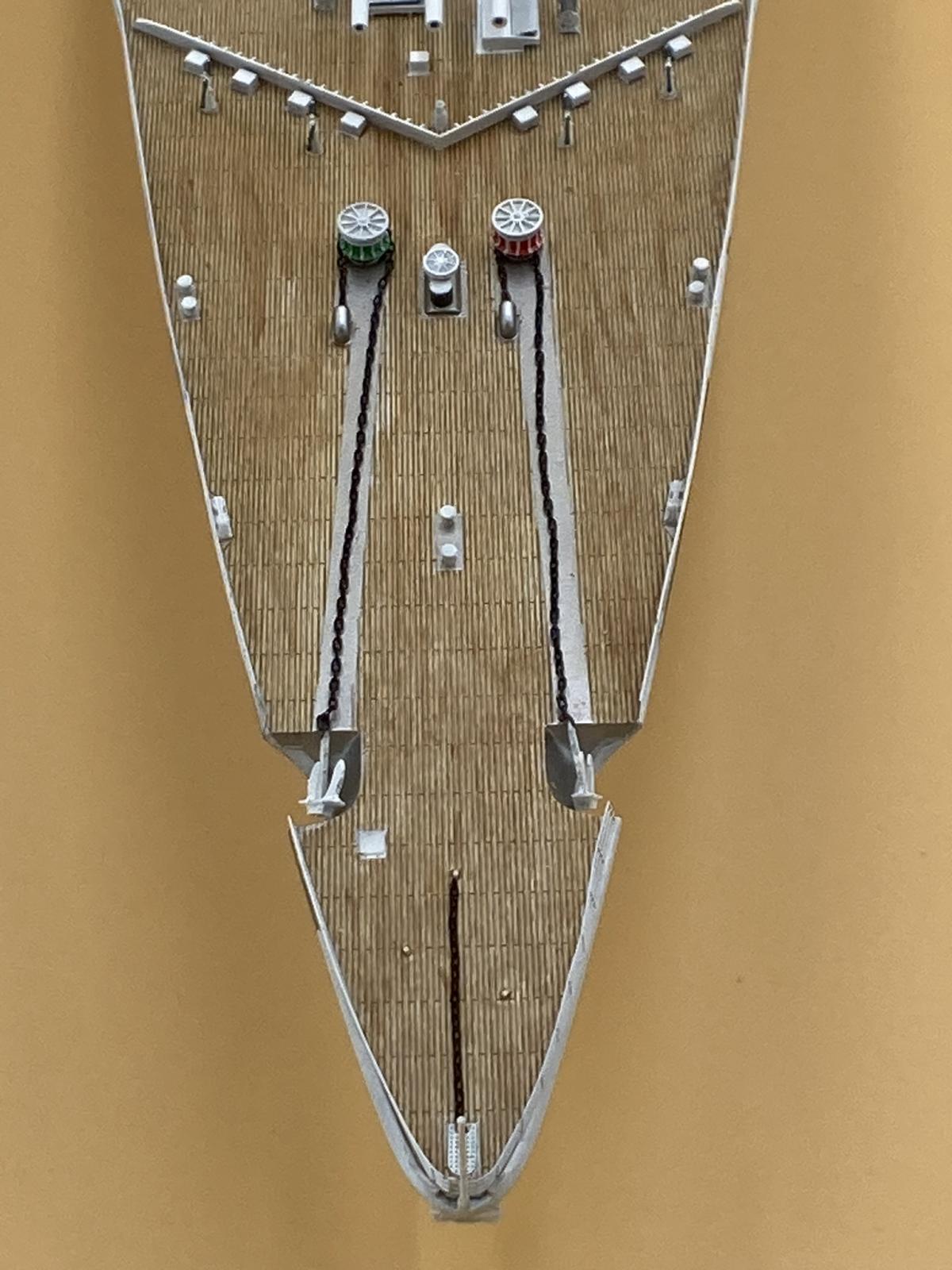
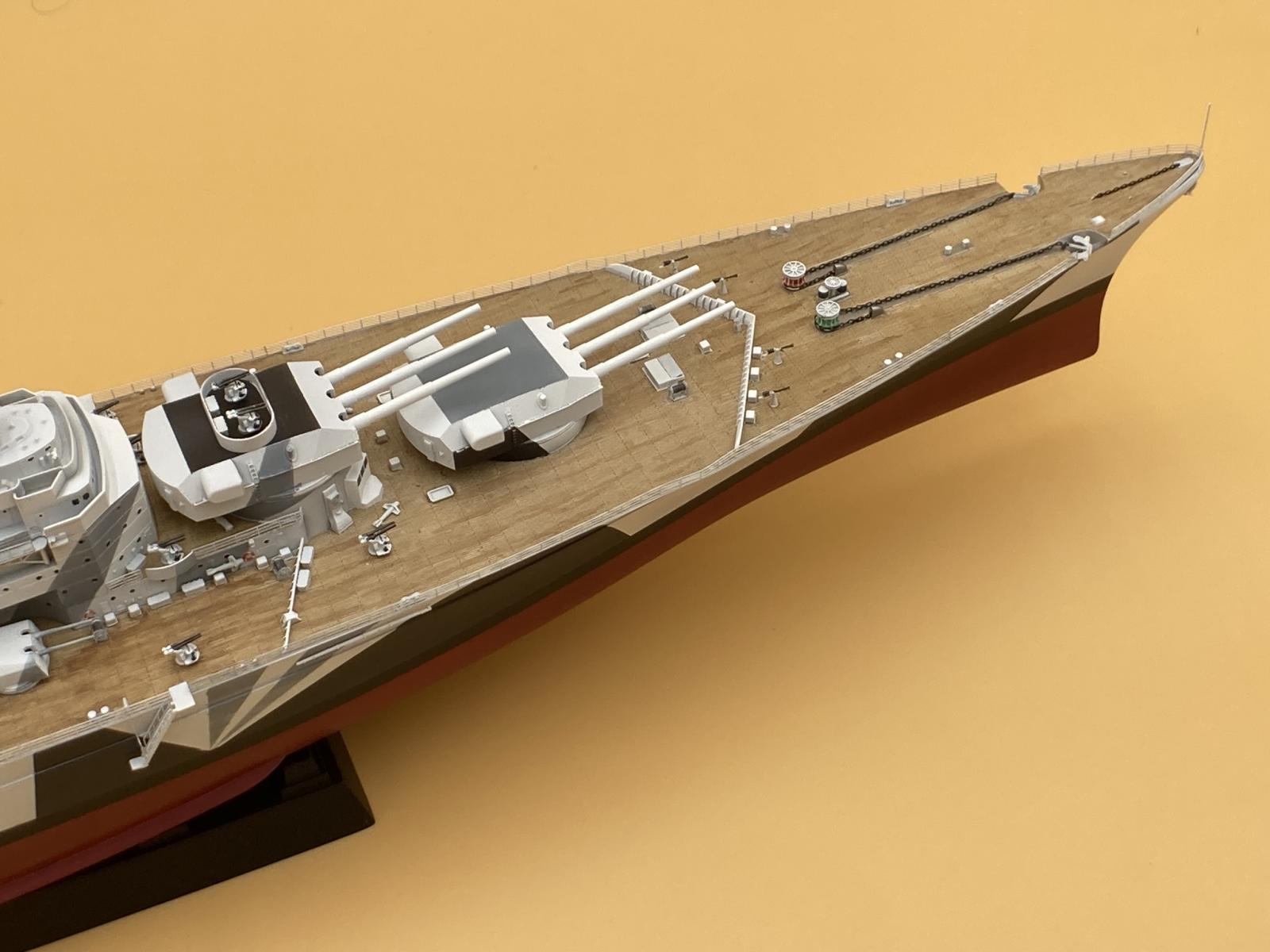
The stern has an anchor chain house but attaching a section of chain between it and the anchor port in the deck is not called out in the instructions. There is plenty of chain so this can be done with parts as supplied in the kit. A German battleship reference is valuable here.
The bow has the cleats for supporting the bow anchor but no reference to doing this is in the instructions. As with the stern deck I opted to install a section of chain to the main cleat. A German battleship reference is valuable here.
The gangway ladders in step 42 and 48 are some of the finest molded parts I’ve seen in this scale. The plastic landing and the support chain have fine pins that mate to the PE ladder. This allows the ladder to rotate so it’s parallel to the deck before final gluing of the mounting points. I was able to successfully build 5 of 6 with out breaking anything. I was totally impressed with the engineering and forming of these parts!
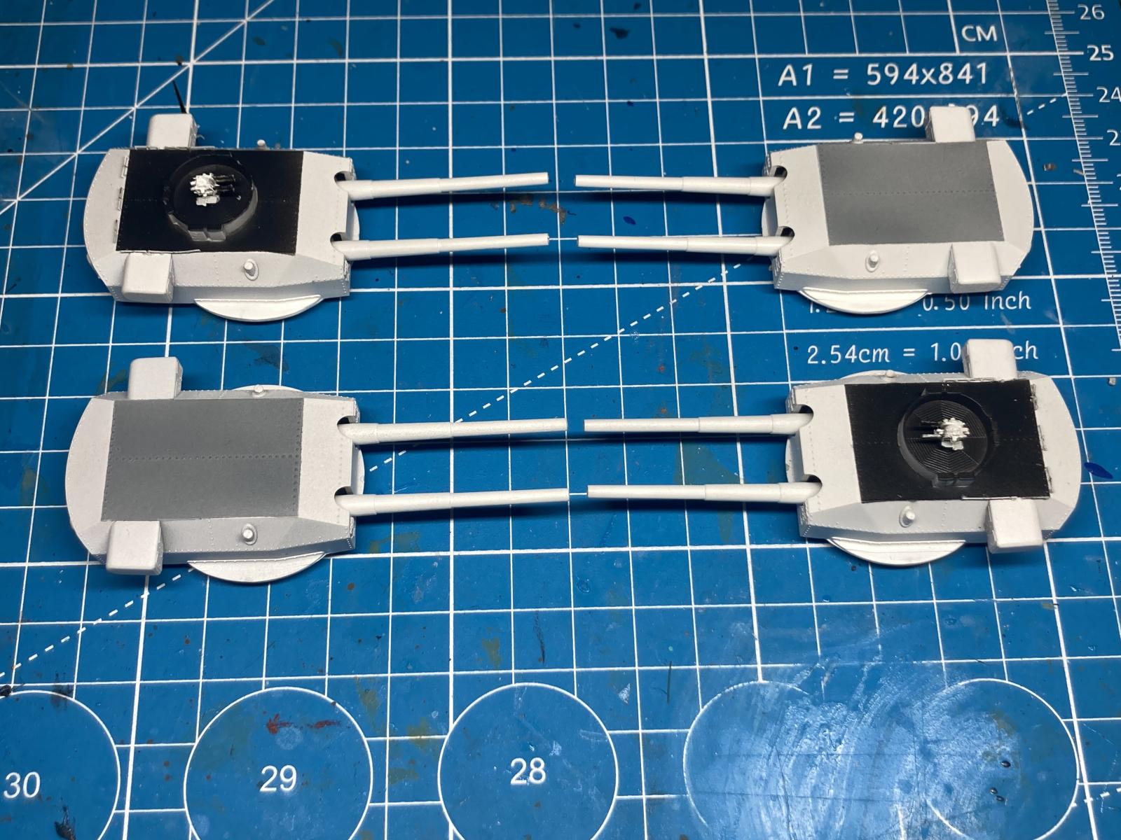
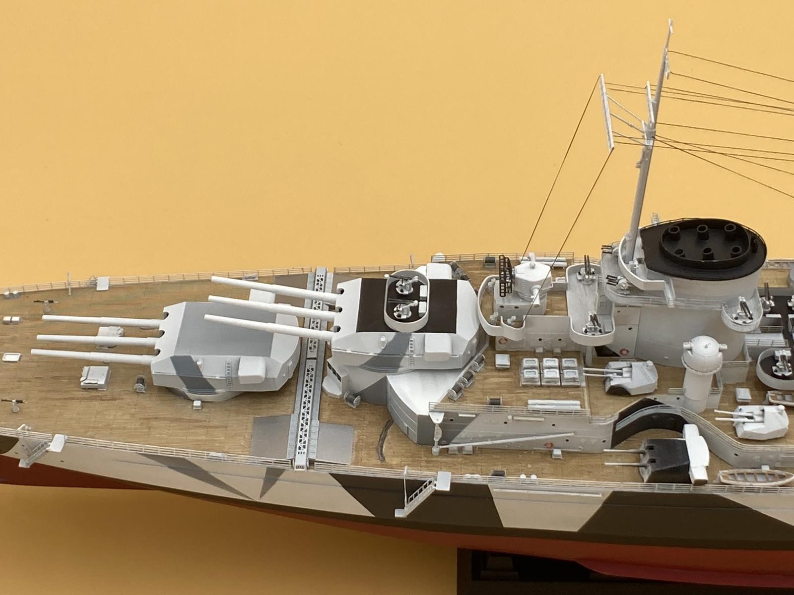
Main Guns
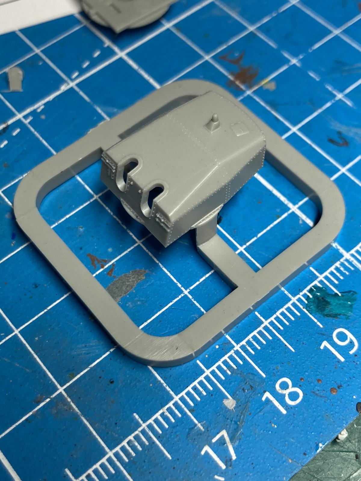
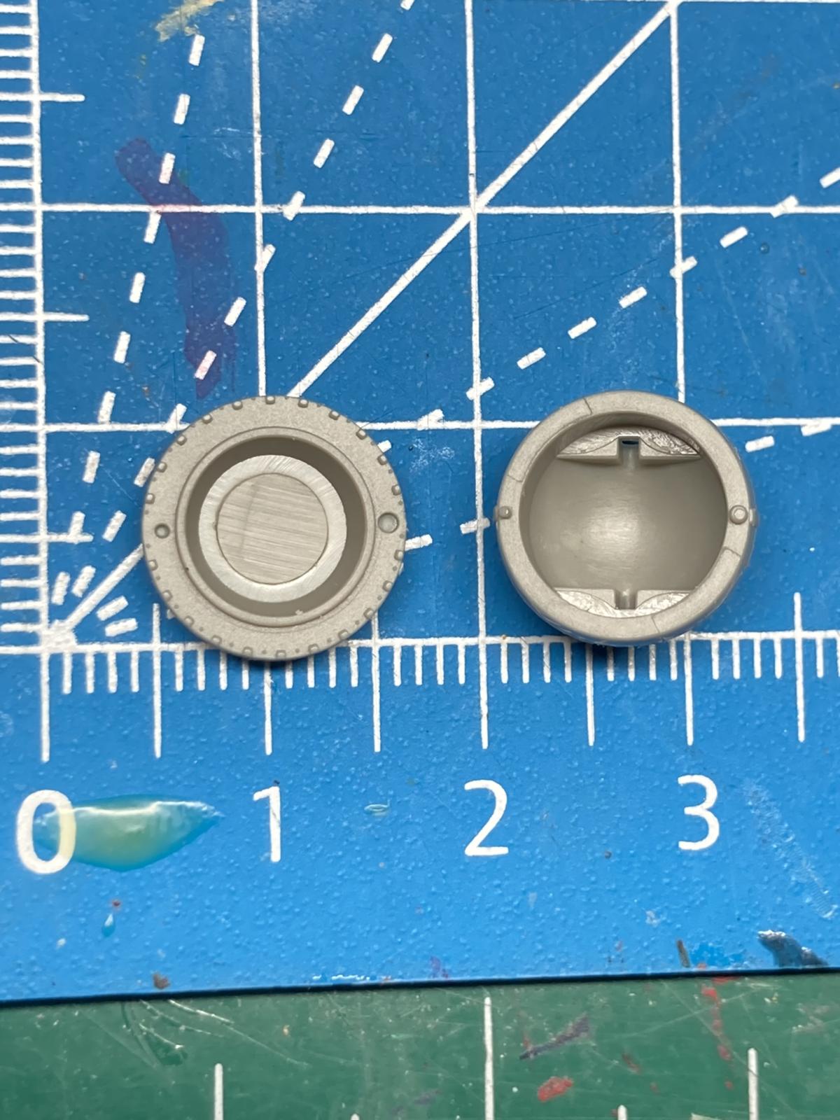
With both molded in rivet detail and the photoetch to add the main guns build to eye catching pieces. Assembly was straight-forward with no surprises or changes to the order of operations. If you’re not brush painting then you’ll have several steps with wait time in-between to finish the assembly. Phot 36 shows the German twin gun turret that I built up but didn’t use on the finished model. The extra step here is to fill and clean up the seam between the top and bottom of each turret. Part C1 has an extension of the rotating assembly on it that would have been better molded with the top as part C4. Be careful removing the range finders, parts C10 & C11, as the sprue gate is on top and having a chunk come off the part when removing it from the sprue results in putty in a location near rivets that are easily sanded off.
AA
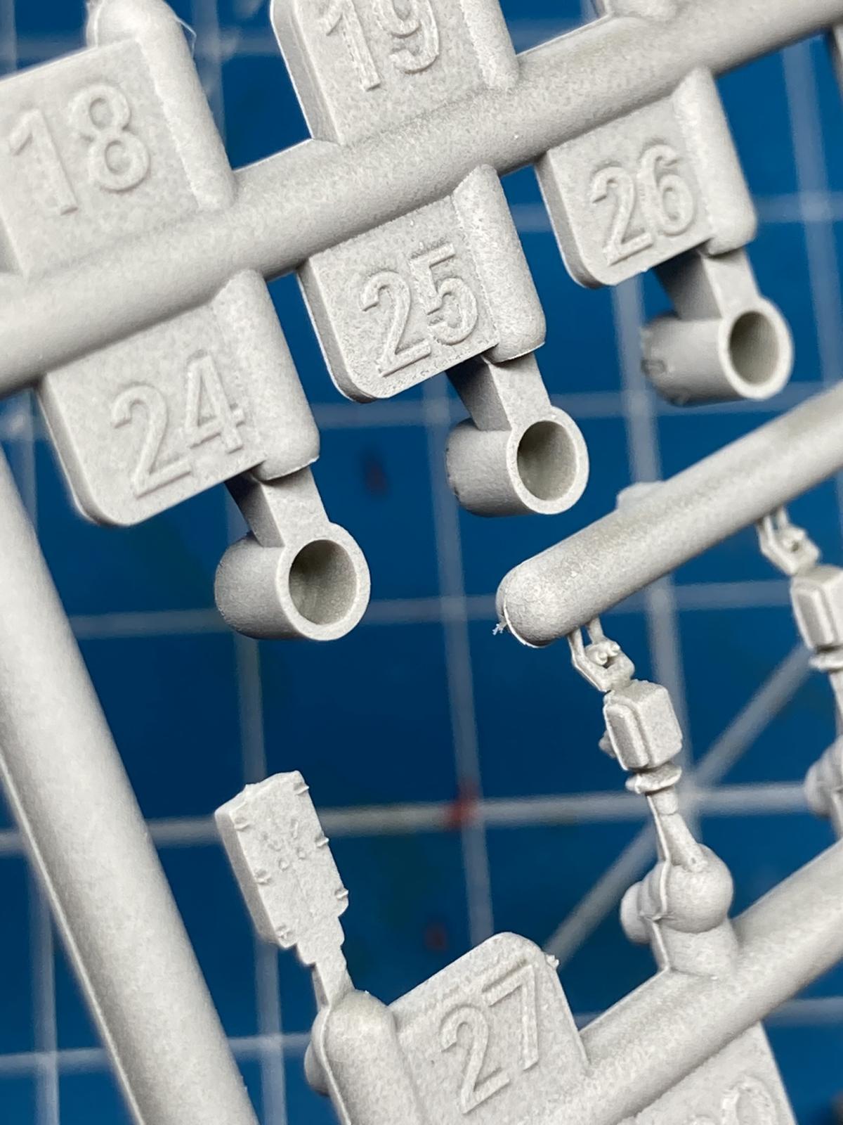
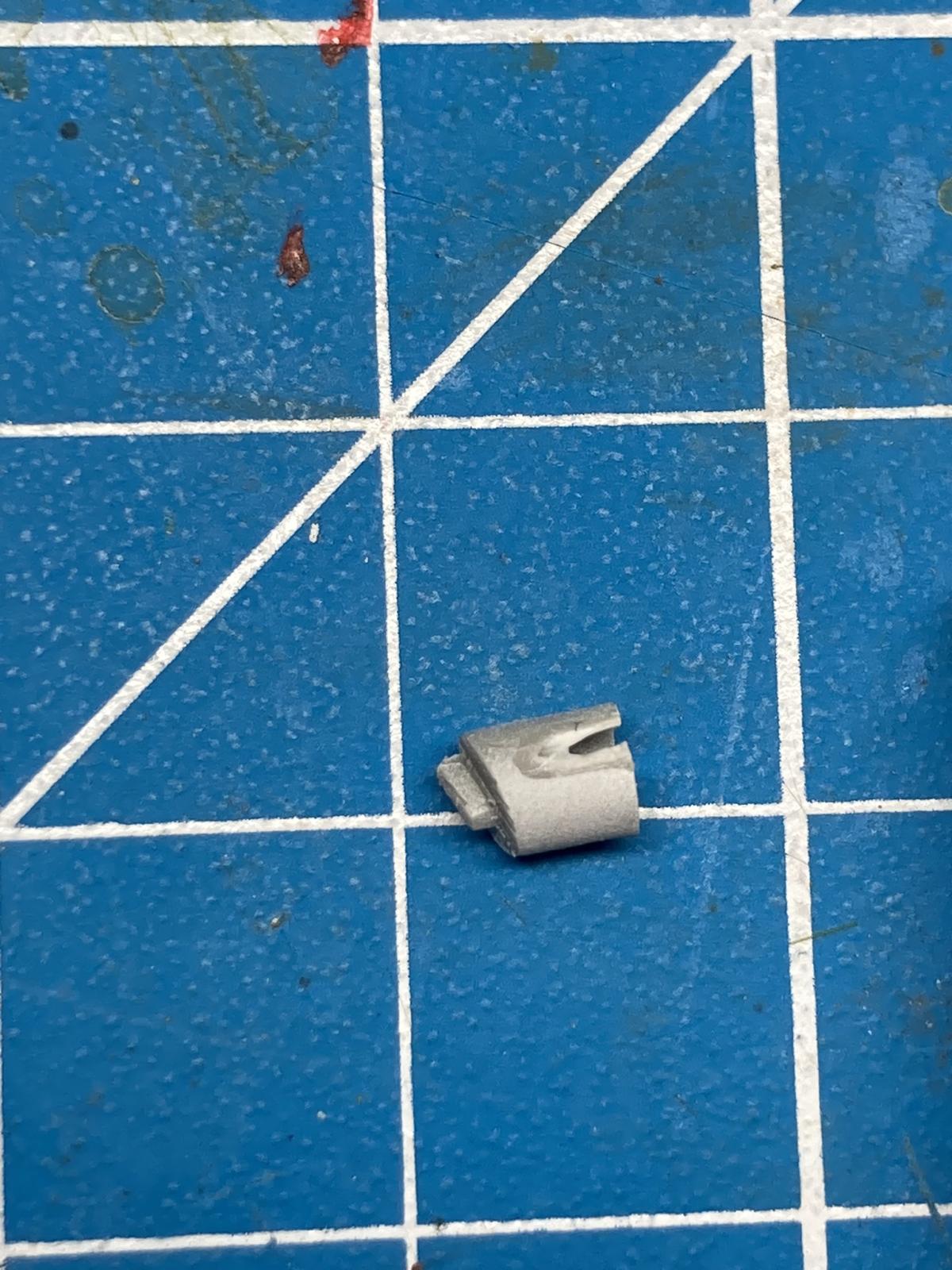
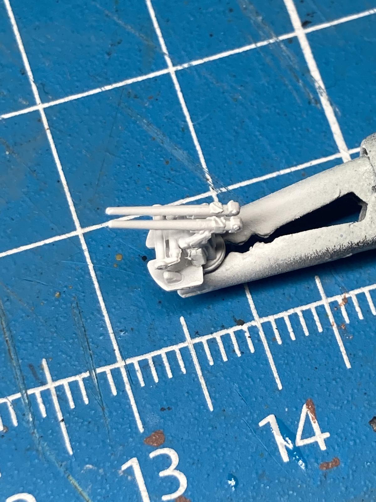
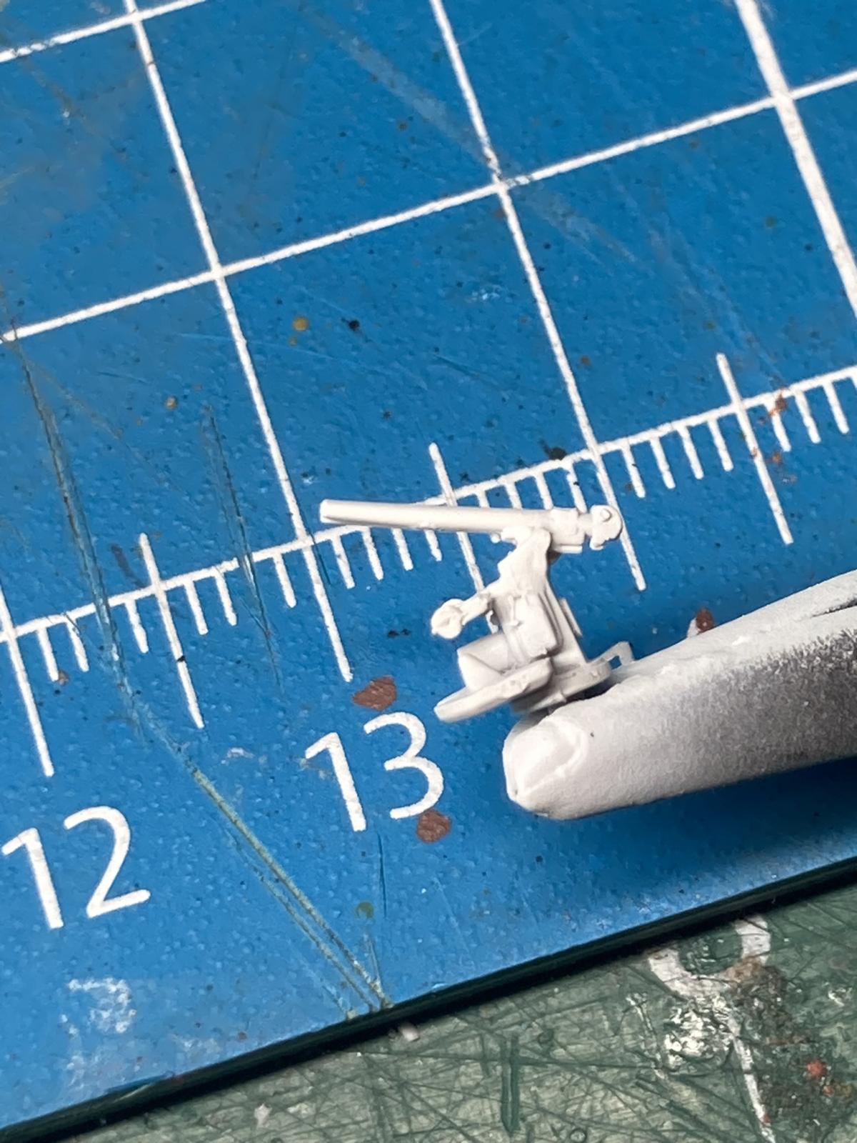
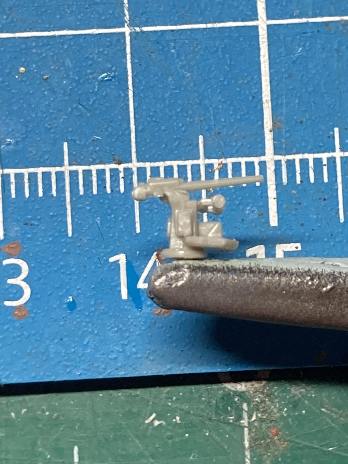
When you get to steps 7 and 8 this kit really shines in this category as seen in photos 23 & 24. The combination of PE and plastic results in very detailed AA. Photo 33 shows the built-up and painted 37mm AA assembly. Note that the guns, parts D31 & 32, are molded slightly different from the picture. I was part way through assembly upon realizing this. Taking a picture and blowing it up to see the shape helped straighten it out (see photo 25 & 26 for correct orientation). In this case having a good reference for the actual equipment is helpful in construction.
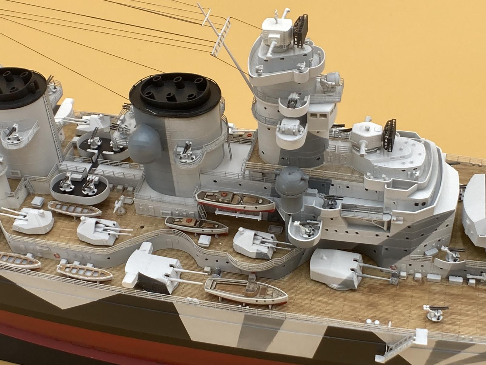
Superstructure
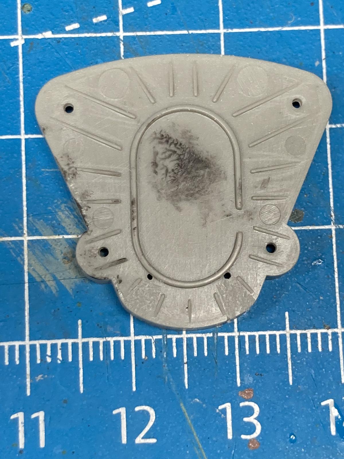
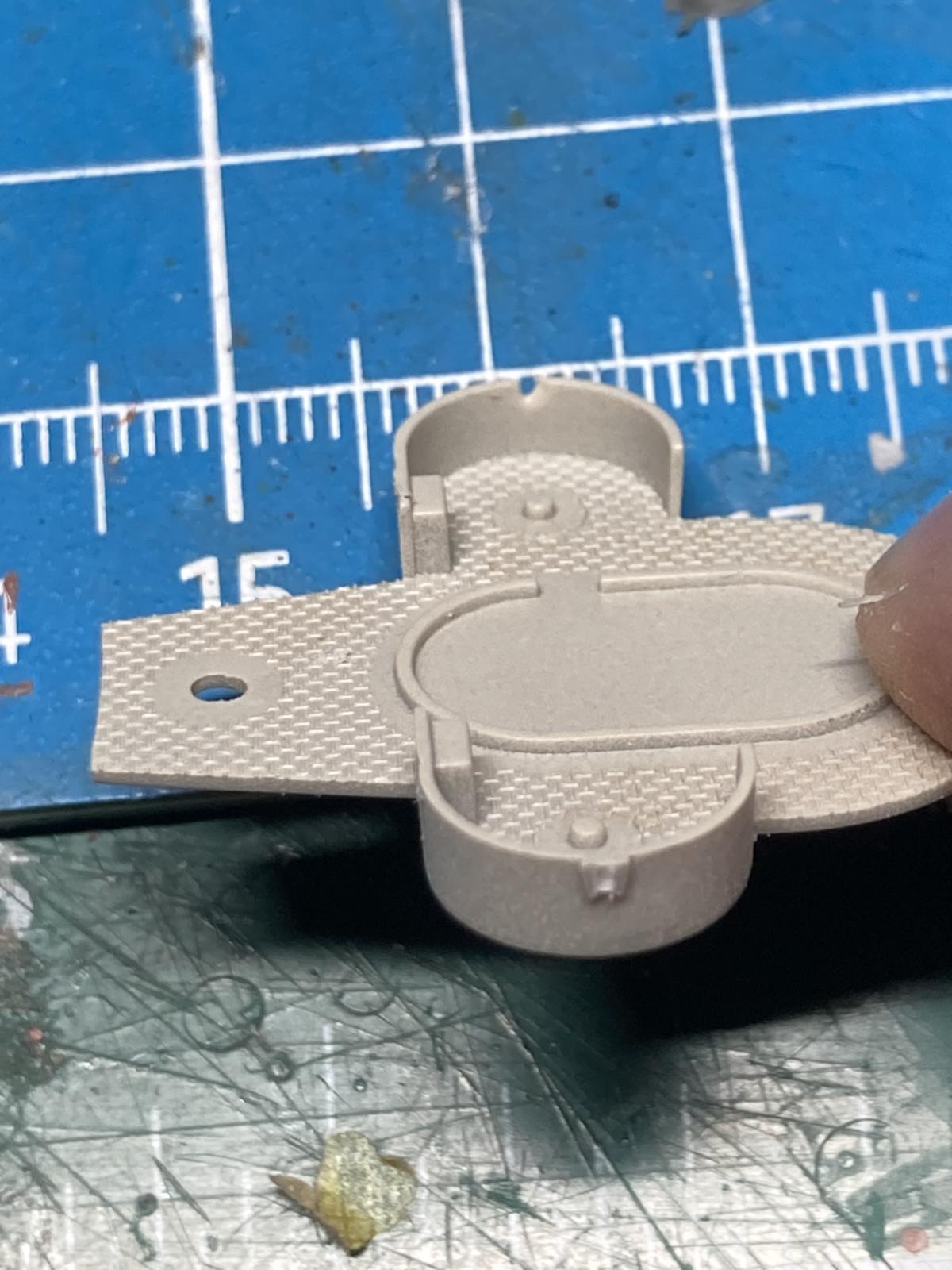
Funnel assembly goes as planned in the instructions. The seams close up and with a little CA and some sanding are invisible on the finished model. The watch-out here is the exhaust stacks and to a lesser degree the decks, parts E24/E28/F10/F25/F26. The sprue gates are huge compared to the part and when cutting them off will take a huge chunk of the stack off with it (see photos 31 through 32). Cut off the sprue itself and file these back to maintain the shape.
Bridge assembly in step 17 goes as indicated in the instructions. Pay close attention to twisting of the structure as you build the individual sections vertically. The fit is so nice that you won’t think it will twist but it will so take a top down look as it is assembled to avoid a twist. I opted to hold off on installing the yard arm until after this section was attached to the deck. The mounting point is solid, so this didn’t impose any issues.
Some individual notes on superstructure assembly:
Intermediate deck F22 in step 26 is extremely flexible so be careful not to break it as you sand off the ejector pin marks and sprue gate connections.
If painting and weathering the deck before assembly, make sure to install the aircraft hangar bay doors ahead of time. Don’t wait till step 33 or the paint work will have to be redone. Also, no reason to clean up these seams as it appears the entre section is made to rotate open on the real battleship. I didn’t make this connection until it was too late so I left the ghost seams, so it appears they are still moveable.
Ladder PE-A61 is very tough to install even during assembly as it connects two separate pieces together. Monday morning quarterbacking my decision I think attaching it to the underside of assembly #24 in step 28 would be the best way to go. Once assembly 24 & 27 are together some PVA glue can be applied to the base of the ladder with a brush.
Trumpeter’s hose reels are way better than other assemblies I’ve done. Will look for these individually for other builds.
When installing the range finders that are built up in steps 10-12 make sure they are aligned parallel with the deck. I noted a twist to them that is just a result of how the top dome fits in the cylinder so alignment is key to this assembly.
The AA mounts in step 33, parts E32 & 33, have PE supports under them that need positioned so they mate up to the superstructure when installed. There are alignment grooves in the parts but they won’t result in the supports meeting the superstructure if you place them exactly in the grooves.
Riling section PE-A9 in step 23 appears too long on both sides. It ends up going almost all the way across the stack but not quite enough to meet up with the opposing PE railing on the other side. The reason is that there is a ladder installed between these railings during step 33.
The 1st level deck railing, PE-A17 & 18, can actually be installed as one single piece. The stations end up perfectly aligned with the direction changes in the deck.
The main hoist rigging for the cranes, PE-B10, looks great on the fret however once it’s removed has a high tendency to deform and no longer look straight, or even that it’s under tension.
In step 50 & 56 the assembly of B2 and PE-B12 is unclear. As it turns out PE-B12 mounts directly to the underside of the wheel of part B2. A German battleship reference is valuable here.
Aircraft launch rails are a might confusing. Step 41 shows the parts the way they are supposed to be bent. Unfortunately, PE-B28 was made upside down so it can never be bent to match the instructions. Also, there is no end plate as shown in the instructions as part of PE-B28 which also makes assembly confusing. Look ahead at step 47 and you will see how it looks as supplied on the fret. A German battleship reference is valuable here.
Aircraft look good on the sprue but are tough to assemble. The clear plastic is brittle by nature and 2 of the 4 fuselage half broke during assembly. Trimming the halves so they fit the bottom of the aircraft and then fit into the mounts for the float plane wasn’t possible for me. On a positive note the float posts, parts 3/6/10/12, didn’t beak and aligned well. Just be careful to trim the pin on top of each one so that the top part (10 & 12) fits correctly to the bottom part (3 & 6)
Railings, Masts & Rigging
PE railings along the hull, 9 sections of PE-C1, need to be custom fit along the hull. The instructions at step 64 show it in 3 sections which is a bit unrealistic. The other thing to think about ahead of time is how to portray the railings across the gangways and at the bow and stern. If you install the gangways in step 43 & 49 then the railings will need to start and stop at each one as they won’t run across the gangway deck plate.
The design of the masts on an H-39 battleship are just weak when scaled down in plastic. I used cement instead of C to try and keep the joints from being brittle knowing that there would be tension on them when rigging. When rigging the plastic masts I installed guy-wires before connecting any of the yard-arms with rigging. A German battleship reference is valuable here. There’s no rigging instructions and I’m sure it is all hypothetical, so no true reference is available. Doing something similar to rigging the Bismarck appeared to work well.
Conclusions
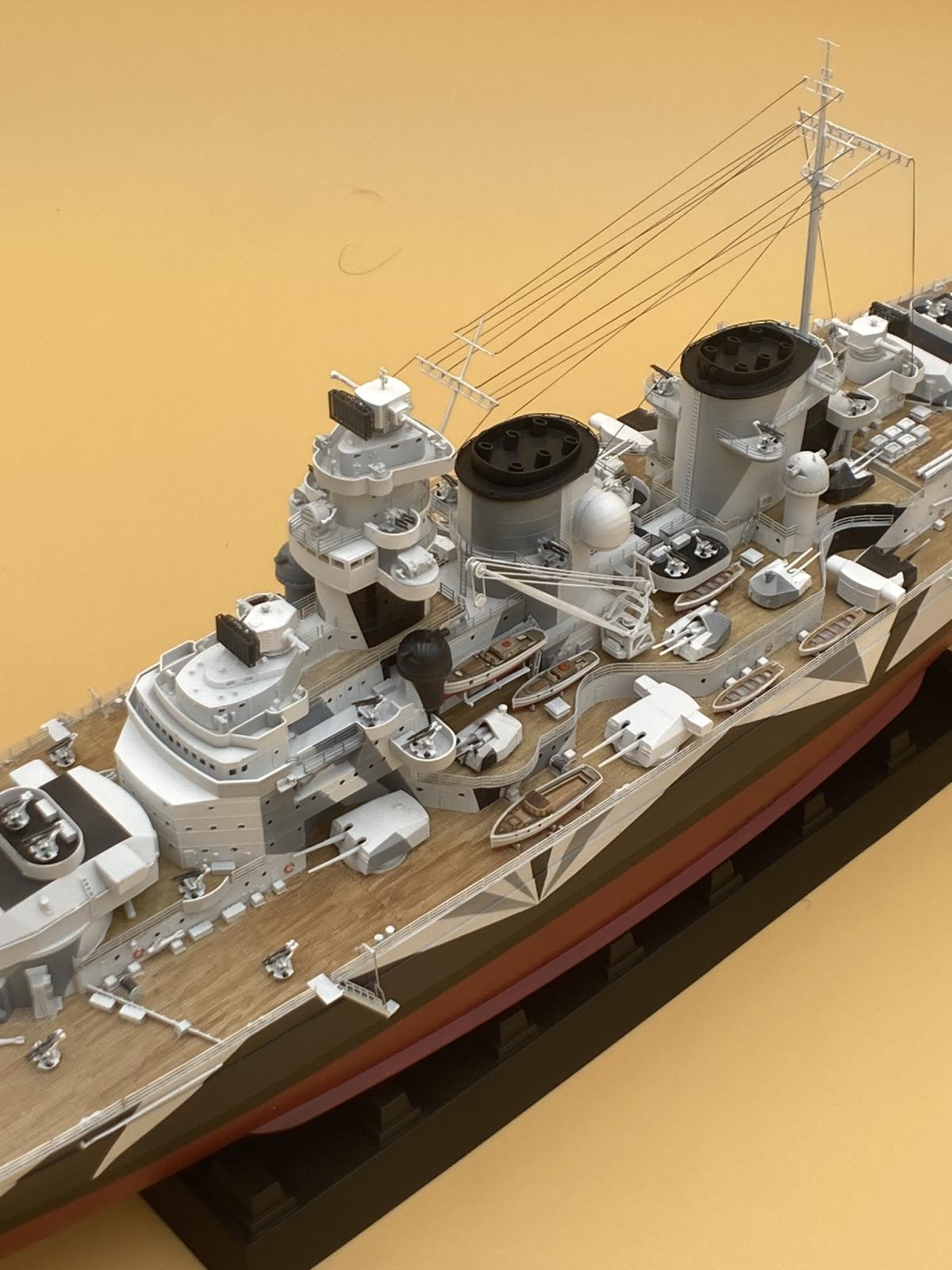
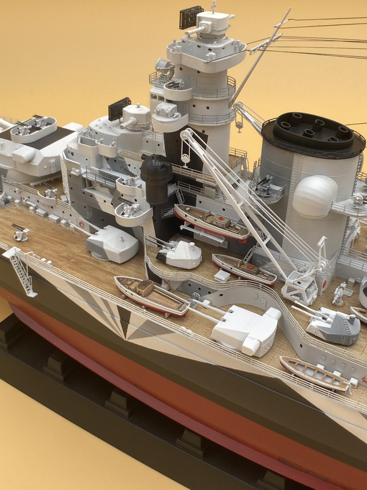
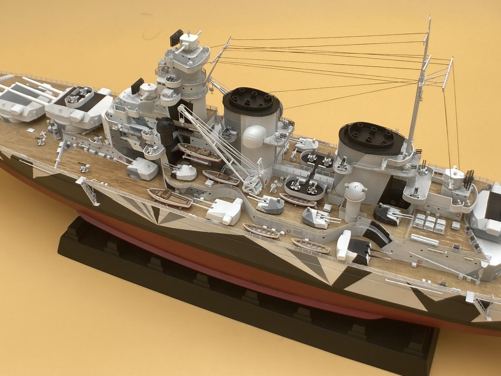
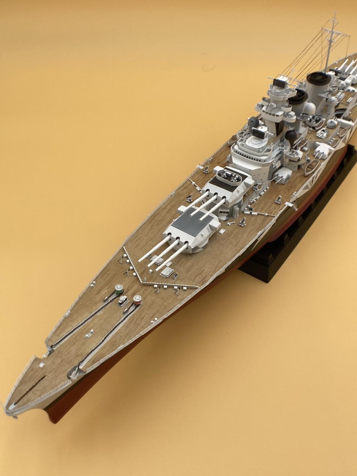
This is a stupendous kit. Built out of the box it makes an impressive display piece. Engineering and fit are top-notch making the build enjoyable, and dare I say relaxing. The PE was a large part of that, being easily removed from the fret and formable without any issues of bends breaking away and needing repaired. The parts count is large and what’s nice is that a vast majority of those parts are used and visible on the model. Check out photos 1-16 of the finished model. You’ll find yourself wanting a ship case just for this beauty when finished!
Many, many, thanks go out to MRC for supplying this Trumpeter model to the IPMS Reviewer Corp! I’d also like to thank IPMS for their efforts in organizing everything and getting it boxed up and shipped out to me for the build.

Ejector Pins
Sprue Gate Issue
Sprue Gate Issue 2
Sprue Gate Issue 3
20mm
20mm 2
Funnel Steel Plate
Sprue Gate
AA1
Error Proofed
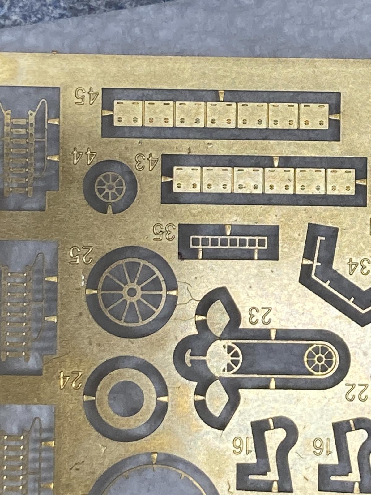
PhotoEtched
Skegs Bare
Skegs Glued
Skegs Primered
Deck Stern Finished
Deck bow Finished
German 16 in Dual
Deck Hull
Bow Anchors

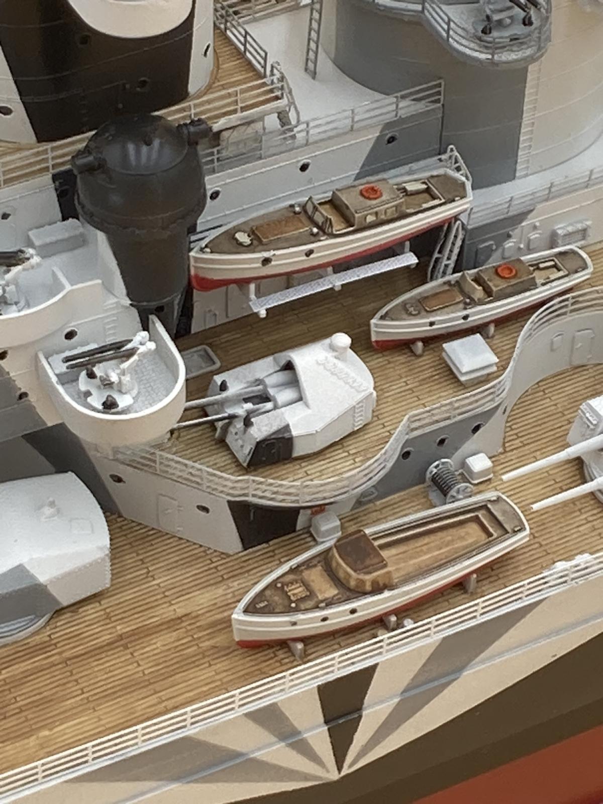
Starboard Yachts
Finished
Finished
Finished
Finished
Finished
Finished
Finished
Finished

Finished

Finished
Finished
Finished
Finished
Finished
Reviewer Bio
Chris Vandegrift

When Chris isn't modeling he's restoring old cars or doing home remodeling in his spare time. Both have helped improve his modeling. "Having learned to paint cars, quite a few of those techniques apply to priming and painting my models," he says. Chris used to build aircraft exclusively, but has expanded into ships, science fiction, armor and cars. A member of multiple IPMS clubs in Ohio including Akron's Ed Kinney Chapter, Wright Field and Cincinnati Scale Modelers, Chris started building models when he was about 7. Chris lives in Cincinnati Ohio; a Mechanical Engineer by trade, he's the head of Operations and Engineering for a company that makes pumps. He's been married to his wife Jane for 30 years; they have four kids ranging from 20 to 34.
Comments
Add new comment
This site is protected by reCAPTCHA and the Google Privacy Policy and Terms of Service apply.
Similar Reviews