
C.S.S. Hunley Civil War Submarine
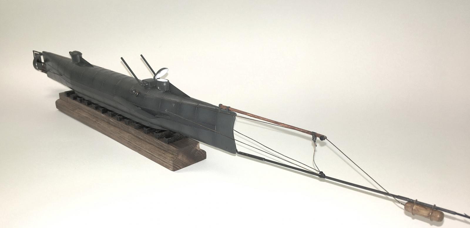
Disclaimer: Mikro-Mir’s 1/35 CSS Hunley is probably one of the more accurate representations of this iconic Civil War submersible. As preservation of the original craft continues, more details come to light regularly. There are numerous interpretations of different features of the boat, and online research probably raised more questions for me than answered them. In the end, I elected to go with my best judgement of how to represent these features, most of which involve the spar torpedo arrangement. It’s also quite possible that the actual configuration changed during the Hunley’s brief career, so my interpretation is just that – an engineering judgement on my part. Here are several websites that may be helpful to you if you elect to build this kit:
https://www.hunley.org/ is the official Hunley website, and well worth a visit
http://wunderkammertales.blogspot.com is one interpretation of the spar torpedo configuration, appears to agree the best with the famous Conrad Chapman painting of 1898, and is the one I used for my build.
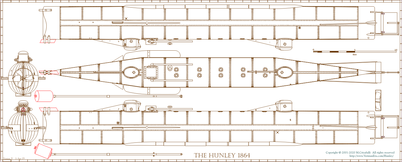
https://www.vernianera.com/Hunley/images/HunleyPlan.png is a downloadable/printable rendering of the submarine done by Michael Crisafulli and may have been the basis for Mikro-Mir’s molds. Very useful for small details such as rudder control arms.
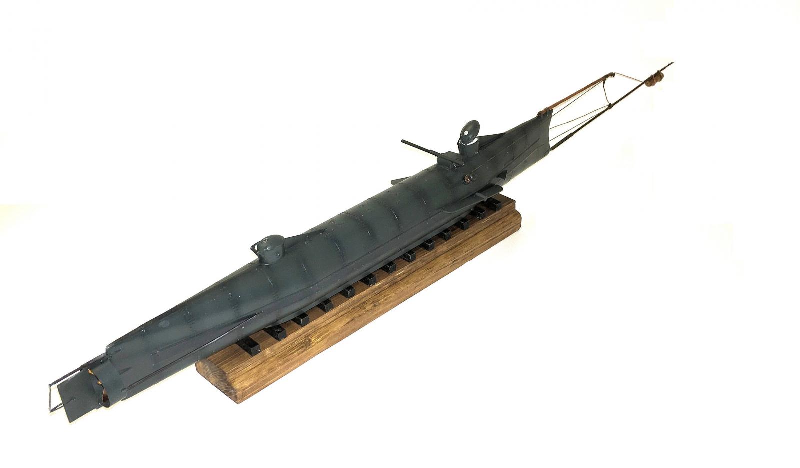
OK, let’s jump into the build, which is fairly straightforward. I cleaned up all of the parts, removing tree stubs and (minimal) flash and started by gluing the hull halves together. Mistake. Both halves are slightly out of round, due no doubt to shrinkage stresses as the plastic cures. The result is a slight “figure 8” shape when joined, which led to a lot of filling and sanding – no big deal on the ballast weight portion of the (lower) hull, but unpleasant to deal with on the top of the hull, where there’s a lot of rivet and porthole detail. Despite my best efforts, I did end up sanding away some of this detail. Fortunately, I was able to restore much of it. I had previously scratch built the USS Alligator, a Union Navy submersible, and I replicated its hull rivets with small dabs of white glue. This trick worked well for me on the hull section joints.
The portholes atop the hull (10 in total) were surrounded by a small raised reinforcing plate and rivet detail. I did not plan to use the kit-supplied clear plastic portholes (more properly, deadlights), preferring to use Micro Kristal Klear after construction was done. There was a postage-stamp sized piece of paper in the small bag of photoetched and clear parts; I discovered that this is actually mask material for the deadlights. The outer ring of each mask was a perfect size to replicate the missing detail and I used the masks as parts, spraying Tamiya primer over the completed hull and sealing them into place.
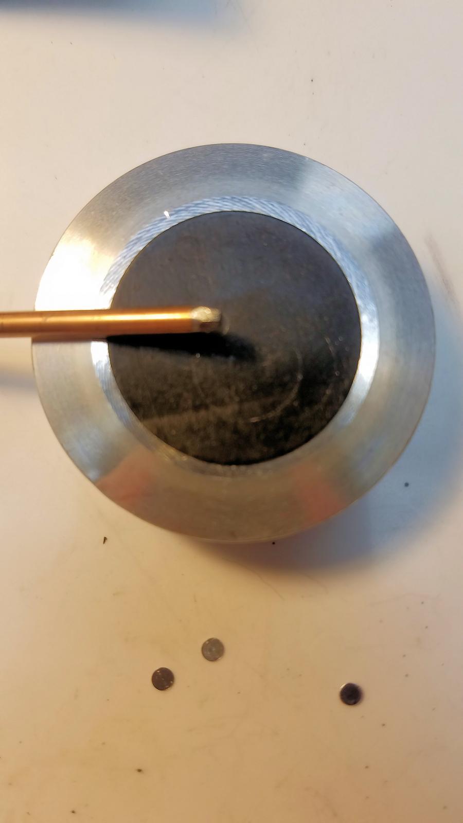
I elected to work on some of the detail parts to take a break from recreating rivet heads, and tackled the propeller assembly next. The kit gives you a plastic prop hub with some very faint markings for location of the three photoetched blades. I chucked the hub into a pin vise to clean up mold lines and stubs, and created a simple paper template with three 1200 radial lines extending out from the center. I cut angled slots into the hub using a razor saw and mounting the blades was a simple task, using slow cure CA to ensure axial and radial alignment using my Mark One calibrated eyeball.
The propeller shroud is unfortunately represented in the kit with two pieces of flat stock that you are to roll and butt-join to create the final part. I couldn’t see myself making that work, so I scrounged around and found a piece of soft copper sheet in my junk box. I calculated the required circumference, cut the strip to size with a small amount of overlap, and used an old drafting circle template as a tool to maintain the circular shape while I superglued the lap joint. I superglued the shroud to the rudder assembly, added the two p/e linkages, primed and painted it, and set the unit aside.
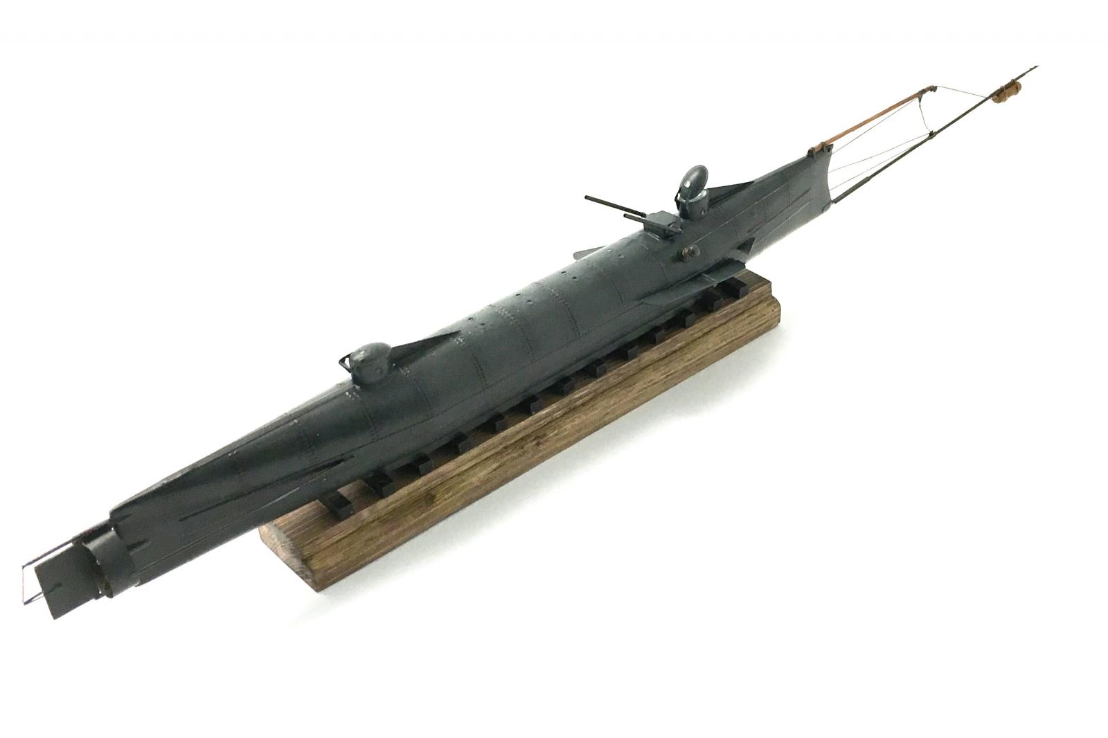
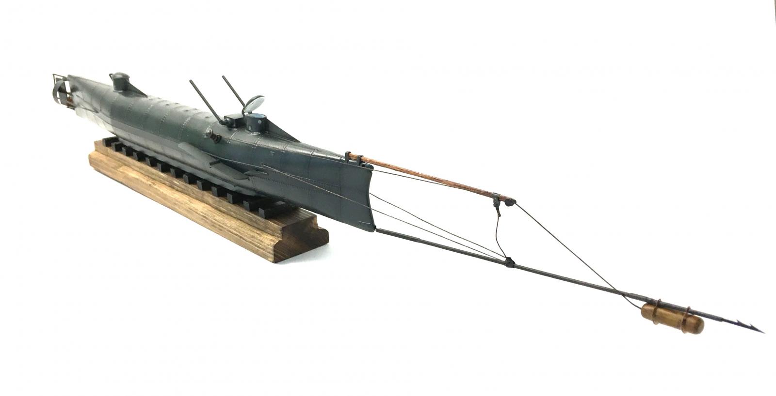
I returned to painting the hull. Results from the deconcretion efforts in the Charleston laboratory suggest that the Hunley’s iron hull was painted black, and that some sort of caulking or sealant is applied at each hull joint location. I opted to use Vallejo Air Black Gray as my base color. After applying this to the entire hull, I went back and added 25% Vallejo Black to the Black Gray base and shot this along all joint lines as well as on the fore-and-aft bands that were added to the Hunley during construction and gave her the oval cross sectional shape. I went back again and sprayed Black Gray with a drop or two of US Gray in the center of each panel and tied everything together with a light overcoat of the base hull color again. I also shot all the remaining parts – diving planes, rudder/shroud assembly, and hatch covers – with the Black Gray color. The hatch covers are molded in clear plastic and I did use the small masks to protect the clear deadlight in each one.
Speaking of hatch covers, Mikro-Mir’s use of photoetch is a mixed blessing. The fiddliest part of the assembly are the 4 separate hinge arms for each hatch. Orienting these is a challenge to say the least. I opted to display one of the hatches open and painted the inside of the cover and the conning tower white. Aligning the hinge pieces was really a challenge – I cut a small wedge shape of balsa wood, taped the hatch and the wedge to the hull, and installed the lower hinge pieces. There are also 4 small p/e lugs that attach to the hull – these could be lifting eyes, but if so, the locations don’t make sense. In any case, they are begging to pop off and join the family of p/e parts living in the carpet in my work area. One did make the trip, never to be seen again. I’d recommend drilling location holes and making these out of thin solder instead.
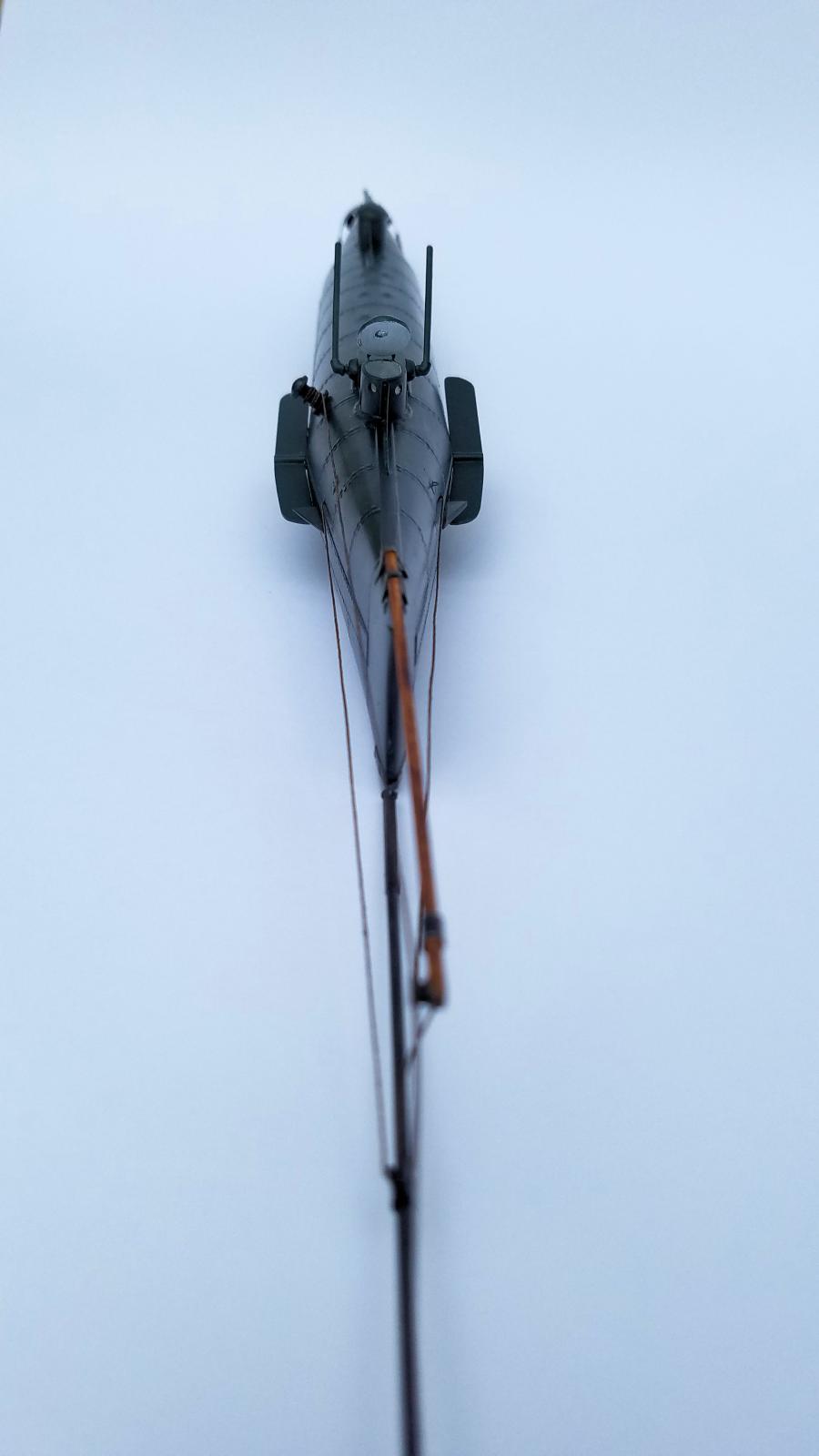
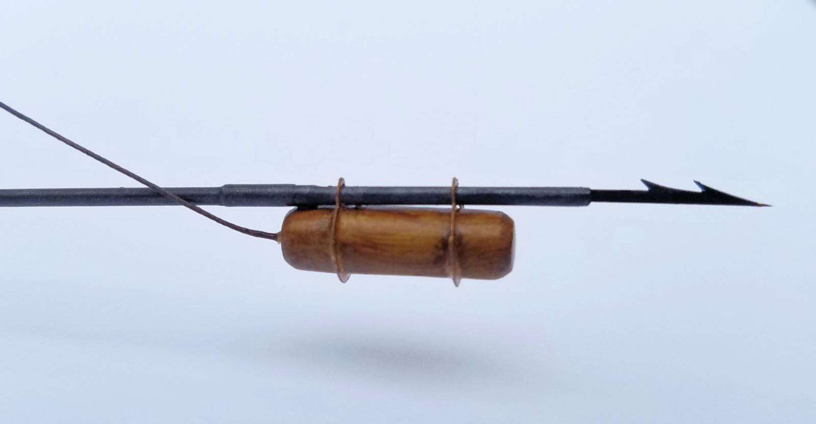
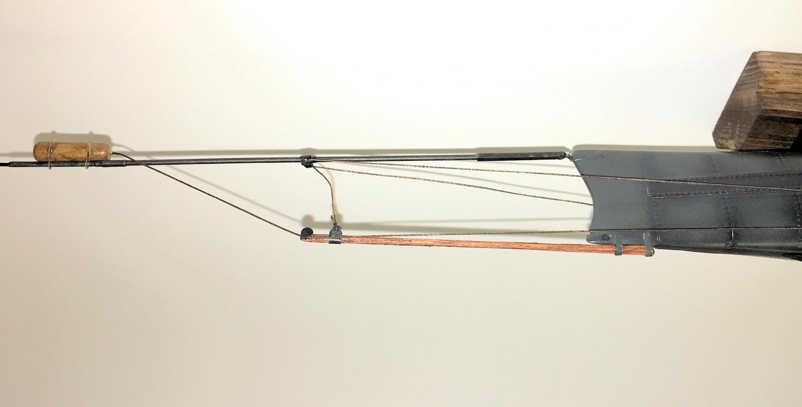
The spar assembly is straightforward. Orienting the two p/e rings that hold the torpedo to the spar is challenging, so I ended up using a piece of plastic rod to simulate the spar while very carefully dabbing bits of thin CA to tack them in place to the torpedo body. I drilled a hole in the aft end of the torpedo (which held 120 lbs. of black powder) to accept the trigger line.
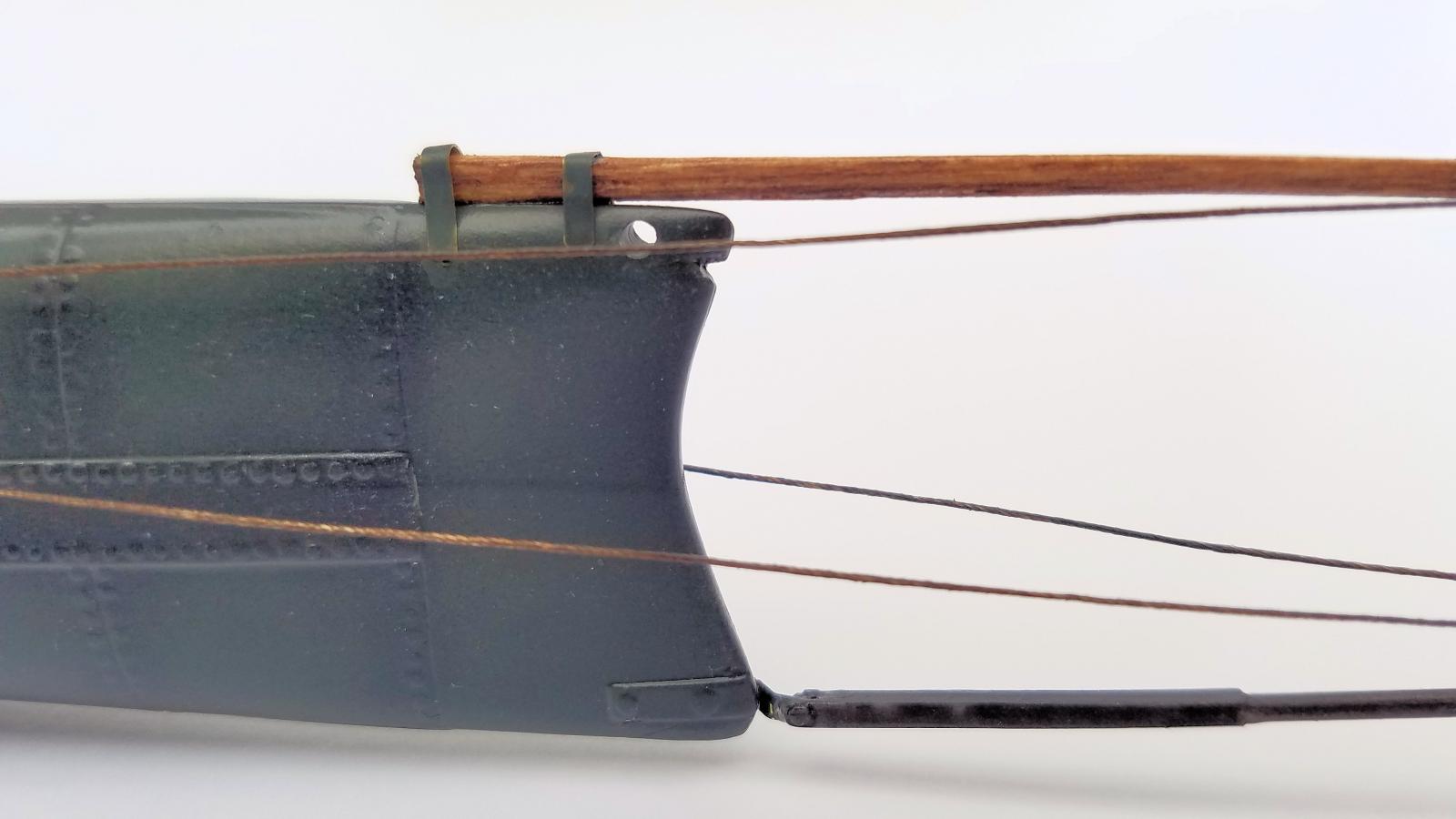
I added the upper support spar by sanding a piece of 1/16 balsa stock into an oval shape, using one of those furniture scratch repair markers to stain it, and applying an overcoat of Pledge Multi-Surface Polish. I cut two scrap pieces of brass from the p/d fret in the kit and made attachment brackets from them. I used my UMM-USA Multi-shape punch set (see my 2016 review of this useful tool) to make a pulley assembly out of thin aluminum sheet, and cut two small brackets to hold the support lines that run to the torpedo spar itself. I used some leftover rigging thread from a sailing ship model, dyed brown with craft paint, to represent these three lines, as well as the trigger line that goes from the back of the torpedo to the starboard external pulley that when wound from inside the sub would trigger the explosion.
That pretty much finished up assembly. I routed a piece of 1” x 2” pine to make a display base, added blocks cut from balsa wood, and glued two brass pins into the lower hull to mount the sub to the base. In 1/35 scale, this is a big model (the spar torpedo assembly is almost as long as the hull).
My thanks go to Mikro-Mir for supplying a nice model of this richly historic vessel to IPMS/USA for review.

Reviewer Bio
John Noack
Modeler since my Dad and I built Aurora biplane box scale kits at the kitchen table. Joined IPMS in the early 1980's and I've held a variety of leadership positions on the Board. I'm a retired VP of Aerospace Engineering, living in the Centerville (Dayton) OH area. I am a Docent at the USAF Museum, a musician in several bands, member of IPMS/WFSM, and a widower.
My tastes are eclectic. When I build aircraft it's usually in 1/72, but I also dabble in submarines, autos, and scratchbuilt Steampunk vehicles.
Comments
Add new comment
This site is protected by reCAPTCHA and the Google Privacy Policy and Terms of Service apply.
Similar Reviews