
Chevrolet G7107 WWII Army Truck
Introduction
This is a new tooling from ICM introduced in 2021 of the iconic Chevrolet G506 truck cast from 100% new molds according to the ICM website.
The following comes directly from their website:
“Delivery of Chevrolet cars to Lend-Lease from the United States began in 1942. Until the end of the war, the number of these vehicles in the Soviet Army exceeded 47,000 units. Thanks to these trucks, the level of mechanization and mobility of combat formations has reached a new level. Chevrolet trucks were used both in combat units and in the rear. They were used to transport infantry, as artillery tractors, ambulances, mobile radios, to deliver ammunition, etc. Reliable enough and easy to operate, maneuverable and with good maneuverability, they rightfully enjoyed the love and respect of the soldiers. Also, in addition to performing the functions of trucks, many vehicles of this series served as the basis for the installation of multiple launch rocket systems – the well-known combat vehicles of rocket artillery, better known as “Katyusha”.
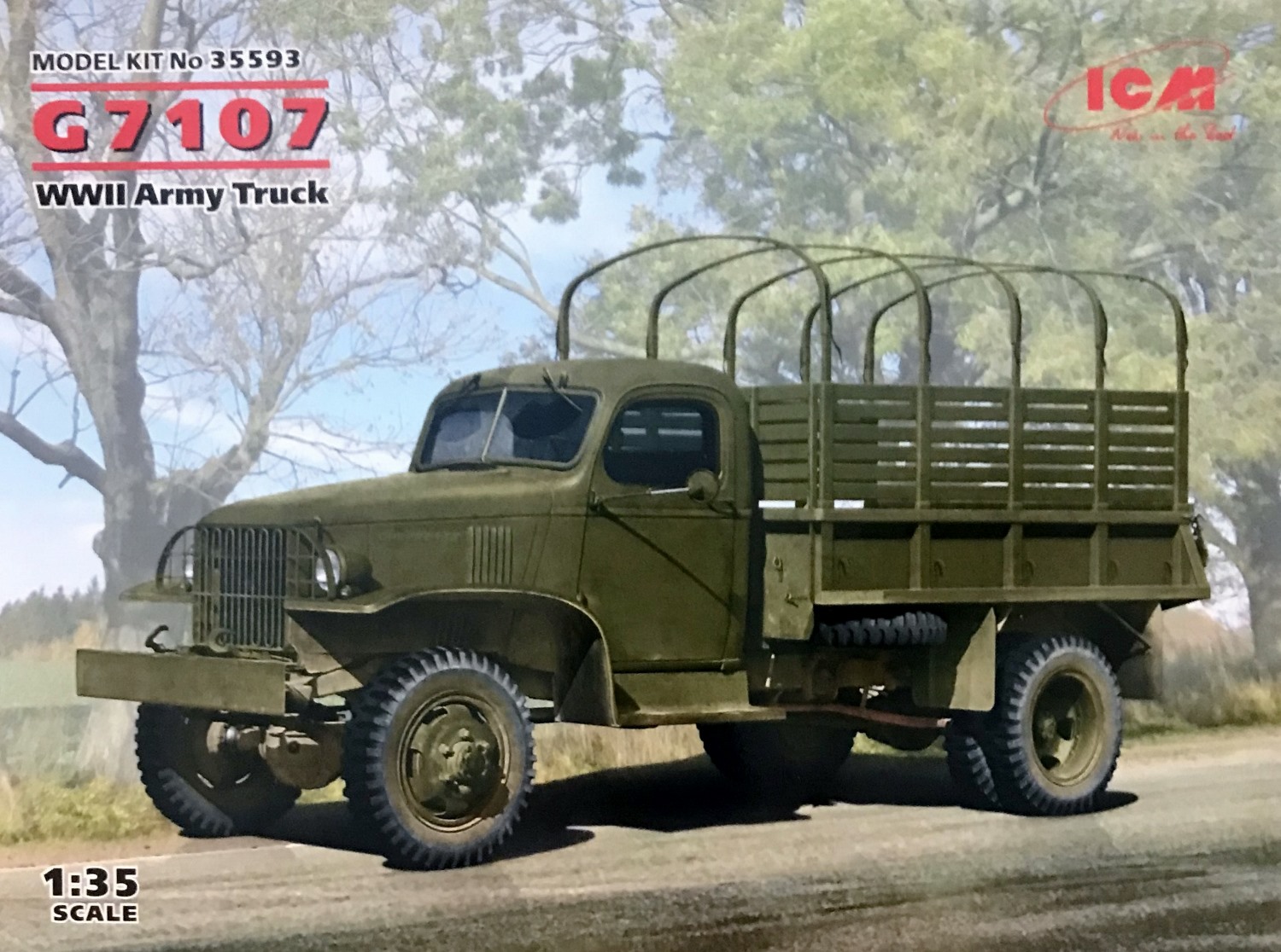
Initially Chevrolet started production with their 1-1/2-ton 4 x 4 trucks in August 1940 with 6 versions. Cargo truck with and without winch, dump truck with and without winch, panel truck and bomb service truck. The vast majority of the 1-1/2 4 x 4 trucks delivered through the Lend-Lease program were Chevrolet’s accounting for over 60,000. When production ended in 1945 twelve versions were produced with the G preface letter. ICM’s G7107 represents a cargo truck without winch and having a short wheel-base of 145 inches.
Box
The box is 12” long x 9” wide x 2-1/4”. It has a colorful overlay with pictures and pertinent information. The inner box is constructed of heavy gauge cardboard, side opening typical lately of ICM marketing of their kits. Inside we find a resealable cellophane bag containing 5 grey sprues, one small bag with clear parts, a small decal sheet and an instructional booklet in portrait fashion. Due to the small parts on the sprues, a better option would be to place each sprue in its separate bag. Although, the kit I received was intact with no damage to the parts.
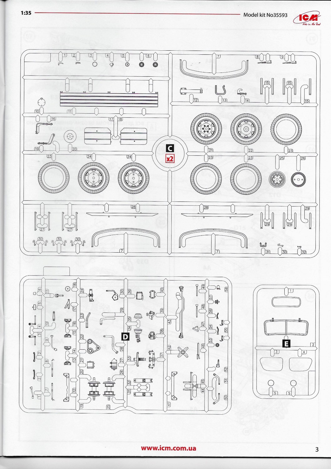
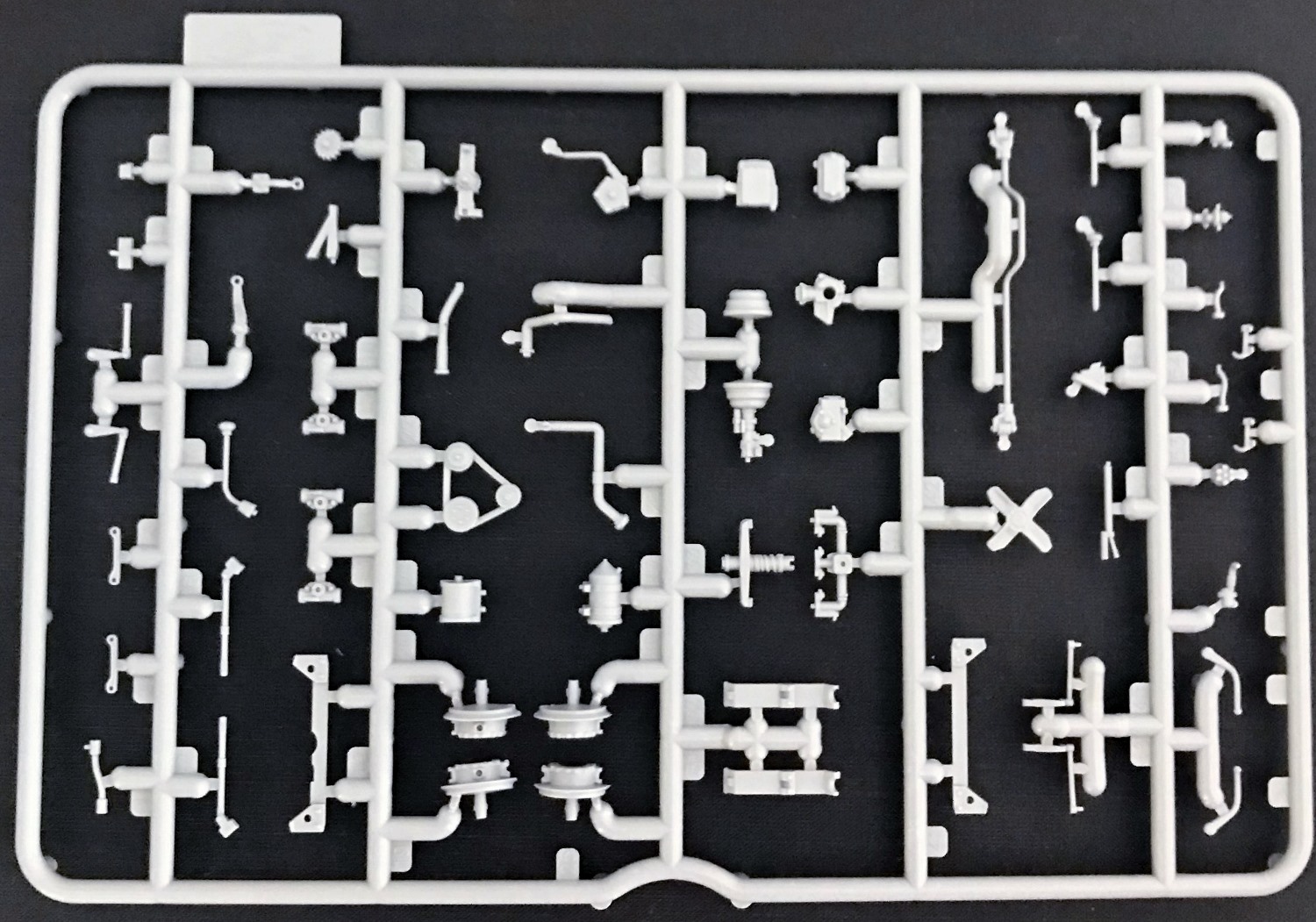
Sprues
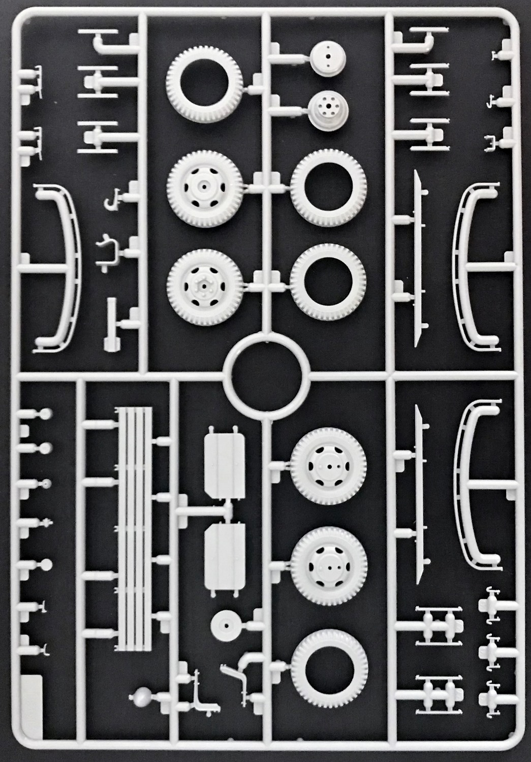
ICM states that this kit is 100% new molds. Upon opening any model kit, what I like to look for is the amount of work, such as mold relief tapers, flashing, ejector pin release points (recessed or elevated marks), mold shift points, sprue attachment / location points and mold seams that need to be addressed during construction. The parts have crisp detail. However, there are several pin release points seen which will have to be sanded or filled. Whether these come into play, I will find out during the construction. The sprues have absolutely zero percent flash and very little seam lines that need to be cleaned up. The attachment points are kept to a minimum and are located in non-discreet areas.
Instruction Manual, Paint/Markings Guide, Decal Sheet
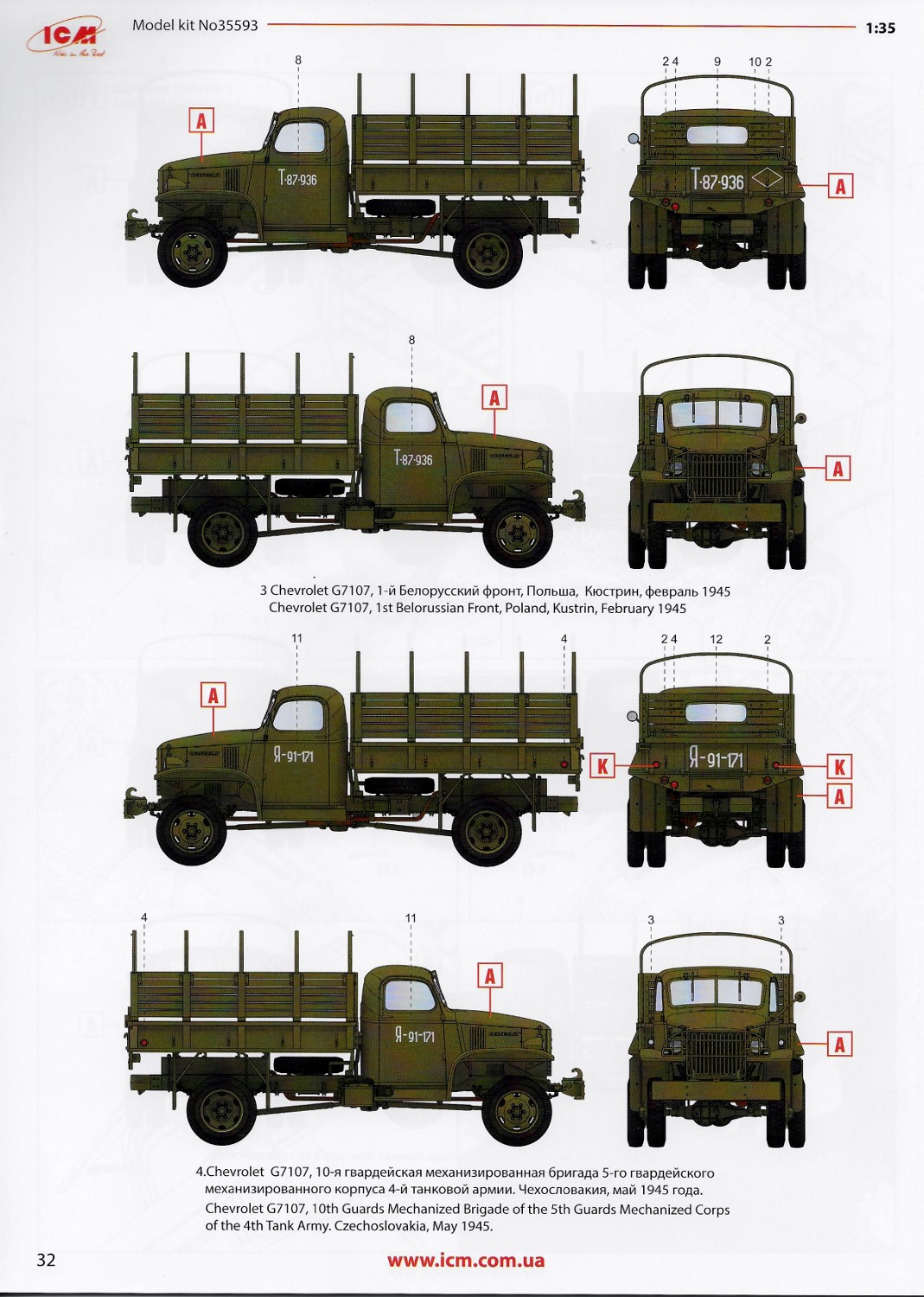
The instruction manual is printed in portrait orientation on 32 pages with 129 steps, albeit most steps involve 1-2 parts. Color call outs include the brands: ICM’s newest paints, Revelle and Tamiya. Also, included in the instructions are images for the parts layout and two pages of markings and painting guides for four vehicles all painted in olive drab.
- Car from a Lend-Lease consignment, 1943.
- Chevrolet G7107,14th Guards Mechanized Brigade of the 4th Guards Mechanized Corps, Yugoslavia, 1944
- Chevrolet G7107,1st Belorussian Front, Poland, Kustrin, February 1945
- Chevrolet G7107,10th Guards Mechanized Brigade of the 5th Guards Mechanized Corps of the 4th Tank Army. Czechoslovakia, May 1945.
The kit has one small decal sheet, but doesn’t include photo-etch. With the detail molded by ICM, photo-etch may not be needed.
The Build
ICM has broken down, more or less, the construction into three (3) basic sub-assemblies allowing the modeler to paint and add detail such as wiring, hoses or the like.
- Chassis and Engine (Steps 1-45)
- Cab, Fenders and Hood (Steps 46-74)
- Cargo Bed and Tires Steps (75-125)
Let me preface my review by stating that as modelers we do not always follow the instructions step by step. We tend to skip around completing steps in advance while letting previous steps dry or bond. For this build and review, I did indeed skip steps, but I will describe what I found in each step, pros or cons, so the builder will be enlightened as to what needs addressed during the build.
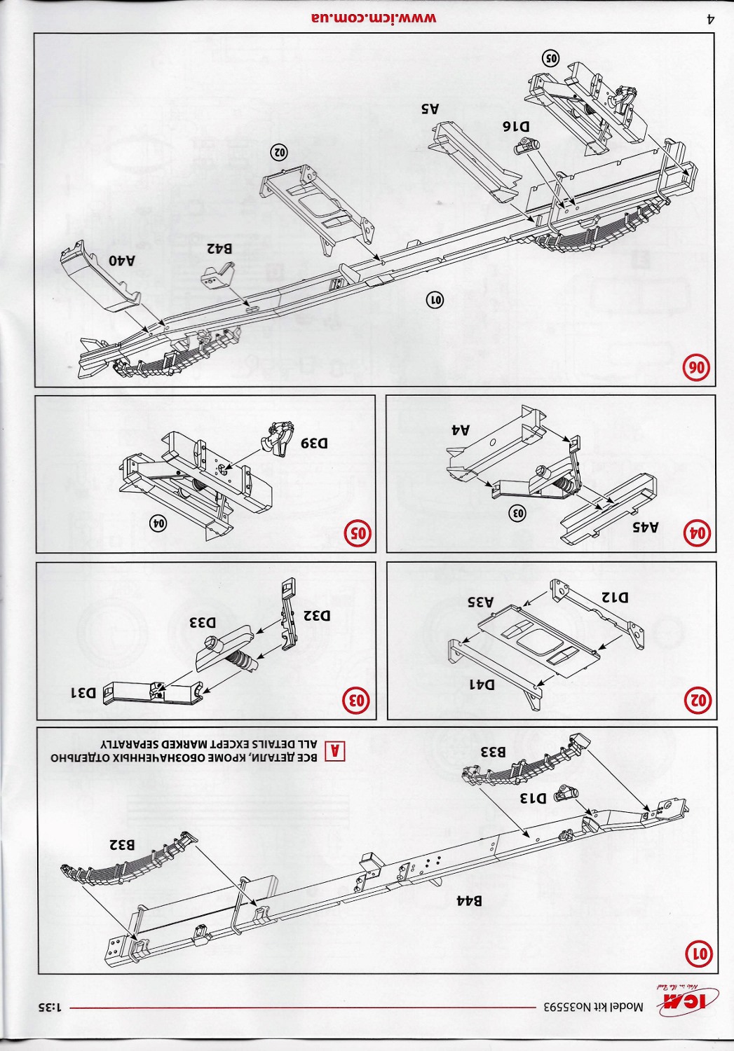
Chassis and Engine
Steps 1-15: These steps consist of the construction of the basic frame. Anyone familiar with building ICM kits will recognize the construction techniques in these steps. ICM uses channel side rails (B1, B44) with cross members and a reinforced rear cross member for the pintle hook. A few ejector release points located on the inner surfaces of the channel rails will have to be sanded. Steering gear, hydraulic shock absorber assemblies (D13, D16, D14 and D15), hydrovac assembly (A46, A47) and a 30-gal gas tank are added to the frame. Minor mold seams and mold shifting on the leaf springs will have to be addressed with filing and sanding. The number of leaves (9 to front and 10 to rear) are molded and correct using TM 9-805 as a reference. In steps 14 and 15 are the construction and placement of the transfer case. *Test fit the front and rear axle propeller shafts before final gluing in the transfer case in step 15.
Steps 16-19: Moving on to the building the front axle assembly ICM has molded excellent detail compared to references. Although the front wheels aren’t molded to articulate, this can be accomplished by minor scratch building and modifications to the steering mechanism. The front wheel hubs combined with the two-piece front brake drum assembly, steering knuckle (part D11), steering knuckle arm, axle shaft and universal joint assemblies allow these modifications to be made. Before gluing the 2-piece front brake assemblies (parts D19, D20, D25 and D26) the direction of the wheels was decided and then the brake assemblies were glued into place. Additionally, ICM provides in step 19 the attachment of the front axle and front axle propeller shaft to the transfer case. The diagram not only shows the placement, but also the positions of the transmission and transmission to the transfer case propeller shaft even though the engine and transmission aren’t assembled until the next step (20). This added information is helpful.
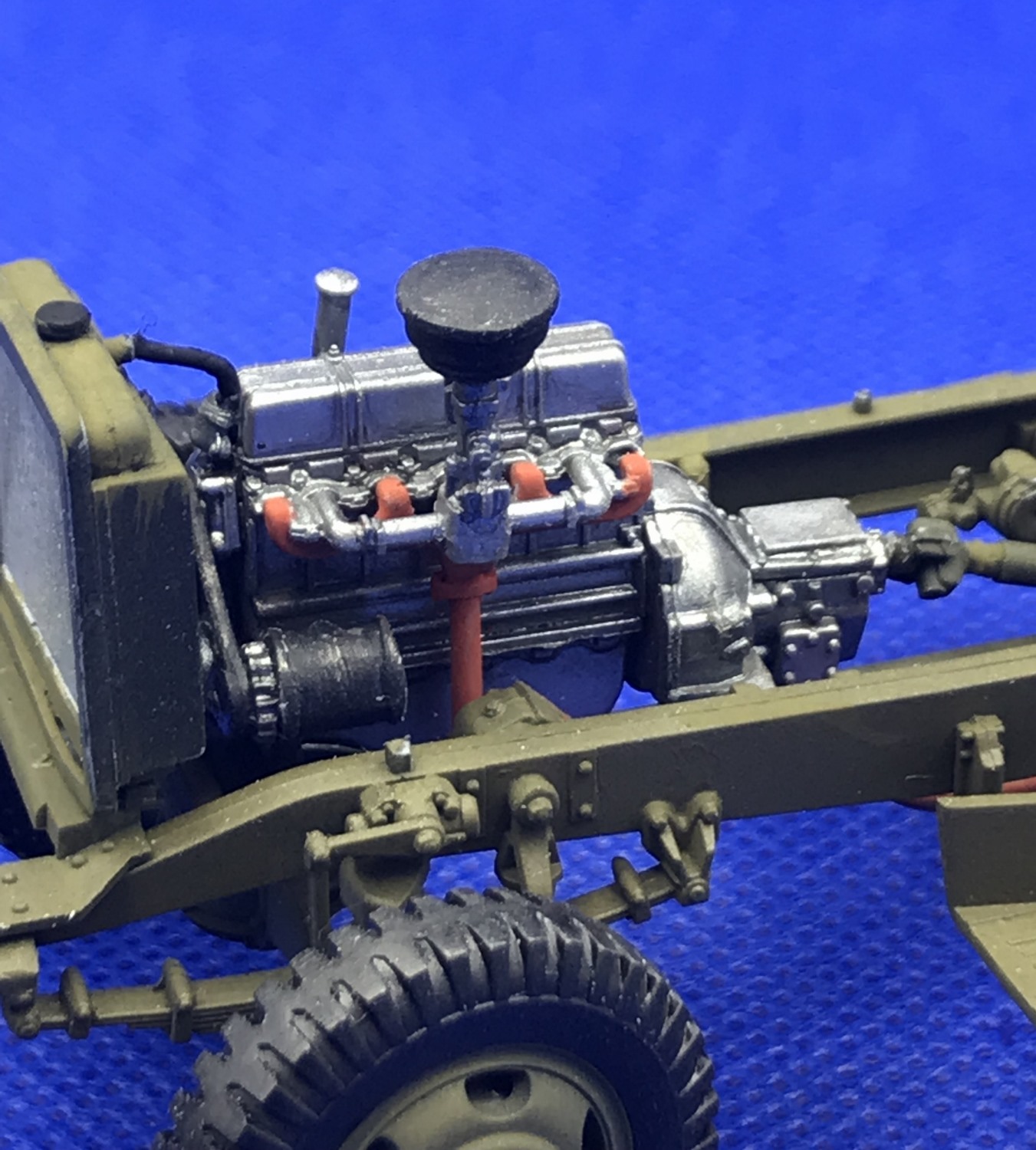
Steps 20-28: With these steps the construction and chassis placement of the BV 1001 4-cycle, gasoline, 6-cylinder, inline, engine is accomplished. Assembly starts with gluing the cylinder halves (parts A9, A12), valve cover (part A7), oil pan (part A34). Transmission assembly (parts B13, B15, D36) is attached to the clutch housing (part A39). Additional small items such as the generator, distributor, fuel pump, thermostat housing, pulley belts and fan are then added to the engine. The thermostat housing (part D52) was left until the radiator was installed in step 67 to ensure proper alignment and placement. Step 28 shows the attachment of the transmission to the transfer case propeller shaft (part B36). I waited until later to make this attachment.
With the completion of the engine, it was time for painting. I primed with black Ammo Mig One Shot Primer then sprayed on a coat of ICM 1025 Natural Steel. As noted earlier, these must be thinned with distilled water or acrylic thinner of your choice. I used distilled water diluting 50%. Small engine parts were hand brushed with ICM 1002 Black. Further engine detailing could be accomplished at this point if the hood is to be shown open by the modeler. The engine has excellent detail and shows well without further work. I waited to install the engine until the until the complete chassis was finished and painted.
Steps 29-34: Returning to the chassis build up, engine placement, and construction of the rear axle in step 29 the attachment of the front cross member occurs. In my build up, I had already constructed the rear axle. Also, in step 32 we see the gluing in of the steering tie rod (part D43). In order to make the steering fully functional the end yokes should be drilled out and a small metal pin installed with plastic washers before gluing to the front wheel hubs. Further detailing and articulation, if one so desires, can be accomplished in step 63 where we see the installation of the pitman arm and steering connector arm.
Steps 35-39: These steps deal with the construction of the 3-piece exhaust system and battery compartment located on the right side of the frame along with hanger sides. Parts B38 and B39. Fuel filter (part D58) is also mounted beside of battery in step 39.
Steps 40-45: The side running boards with frame hangers are constructed here. Tread molding is well done by ICM and should show nicely when painted. Also, in steps 44-45 we see the gluing in of the air cleaner and intake manifold to the engine and finally the addition of the spare tire mount (part B8). Since modelers do not always follow the steps, the exhaust manifold and air cleaner were glued on in step 27 previously.
Cab, Fenders and Hood
Steps 46-56: In these steps the actual construction of the cab begins. The cab consists of multiple parts which fit together leaving a seam line. Some minor sanding and Tamiya putty did the trick. Starting with step 46 the rear-view mirror is added to the headliner. Then on to step 47 the dash and headliner are added. Comparing references to the molded dash, ICM appears to be spot-on with regard to the molding accuracy of the instrument cluster. In steps 50-51 the remaining levers and pedals are added. The seat is made up of 3 sections with some detail to the seat itself. The decal sheet has a decal for the instrument cluster.
Step 57-62: Each of the 2 doors have 4 mold ejector pin marks which need to be filled. The doors could be posed open or shut. The door bottom hinges are molded into the cab while the top hinges are part of the side mirrors as shown in Step 125. The window cranks and door handles are glued on. Wrapping up the cab assembly is the installation of the wind vent, current regulator and oil filter on the firewall in step 60. In step 61 and 62 other small engine parts (cranking motor A1 and oil filler tube D23) are added.
Step 63: In this step is the addition of the pitman arm (D10), steering connector arm (D1) and shock absorber arms (D4) to the frame and front axle making up the remainder of the steering linkage. As previously discussed in steps 29-34, the steering can be made to articulate by making changes to the arms. Otherwise, a matter of attaching these detailed parts.
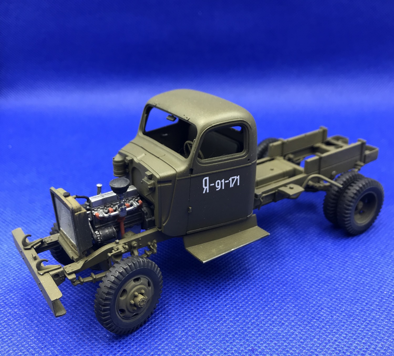
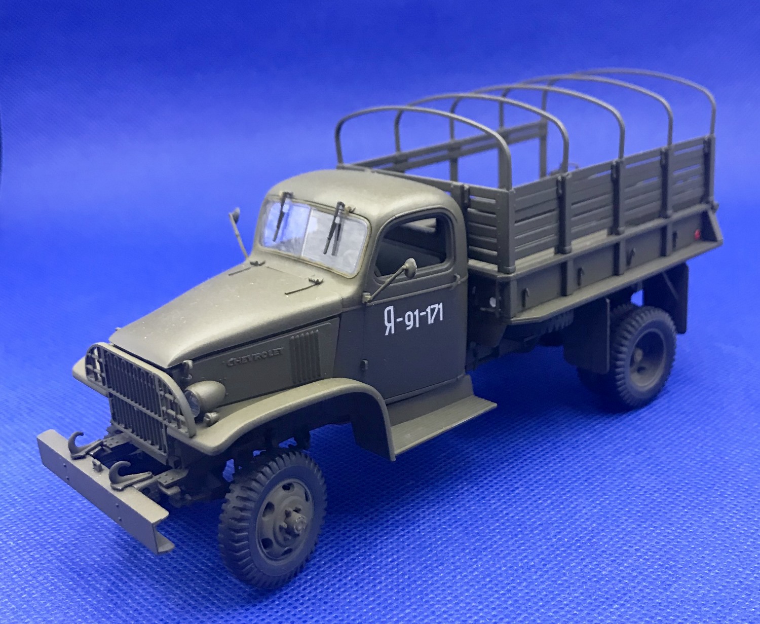
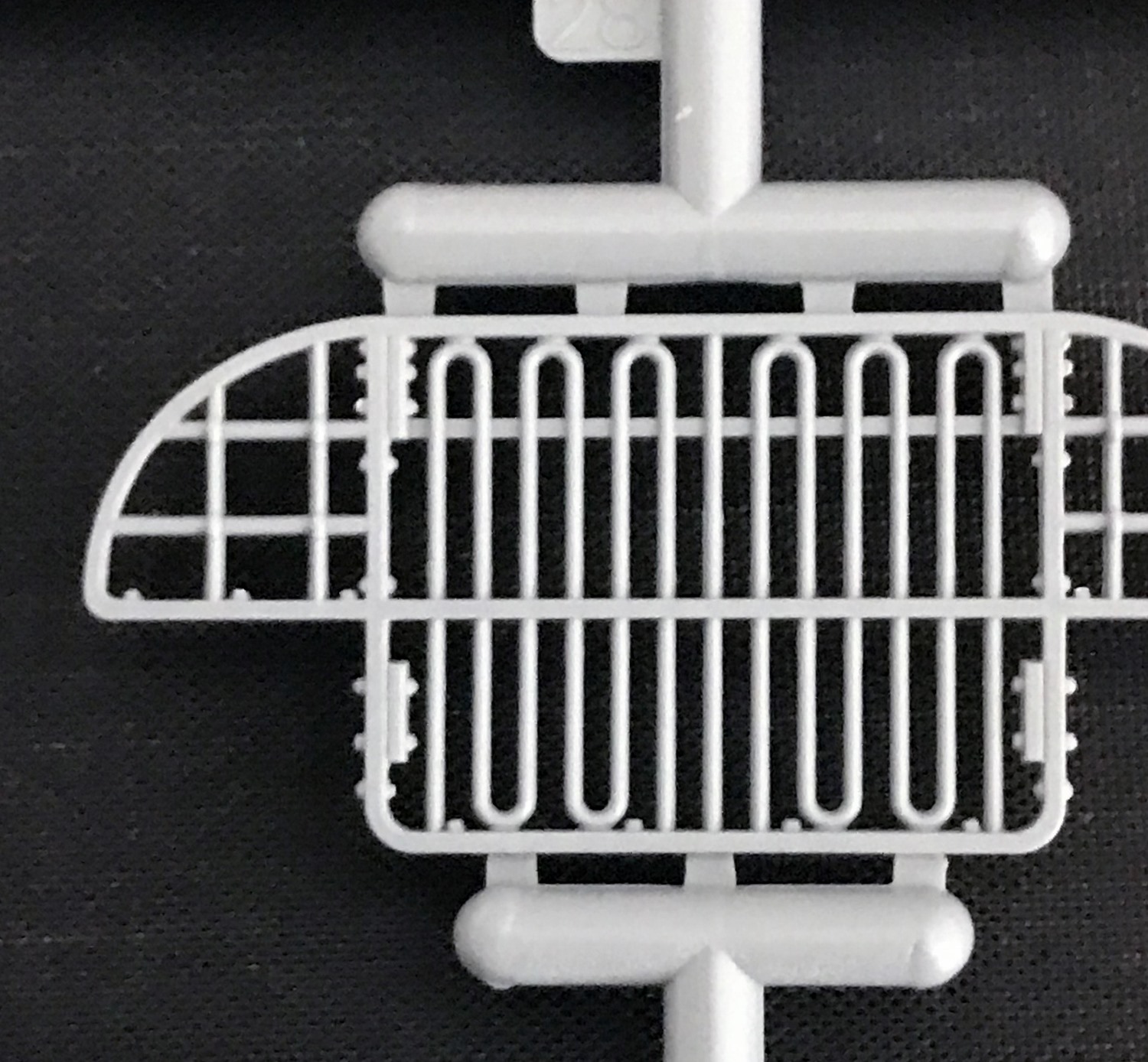
Step 64-74: The 4-part radiator is constructed and attached to the frame. Good detail is present in the radiator vents. The engine hood assemblies, side engine panels, fenders, including the earlier version of the radiator guard assembly are installed in these steps. Step 72 shows the installation of the hood with molded on hinges. Parts layout on page 2 also shows hinges molded onto the hood. Thinking I sanded the hinges off after removing the hood from the sprue, I did a little investigating. The actual photo taken of sprue A before construction began revealed the hinges were not molded on. ICM’s website does show the hinges on the sprue. However, a quick look into other reviews, also did not show the hinges molded on. Scratch building hinges would not be difficult. Using thin plastic card stock and rods, 2 were made and installed on the hood. Another option would be to use photoetch for the hinges. Good detail on the side engine panels with the Chevrolet lettering is present. The 2-part spare tire is glued onto the frame support in step 74.
Cargo Bed and Tires Steps
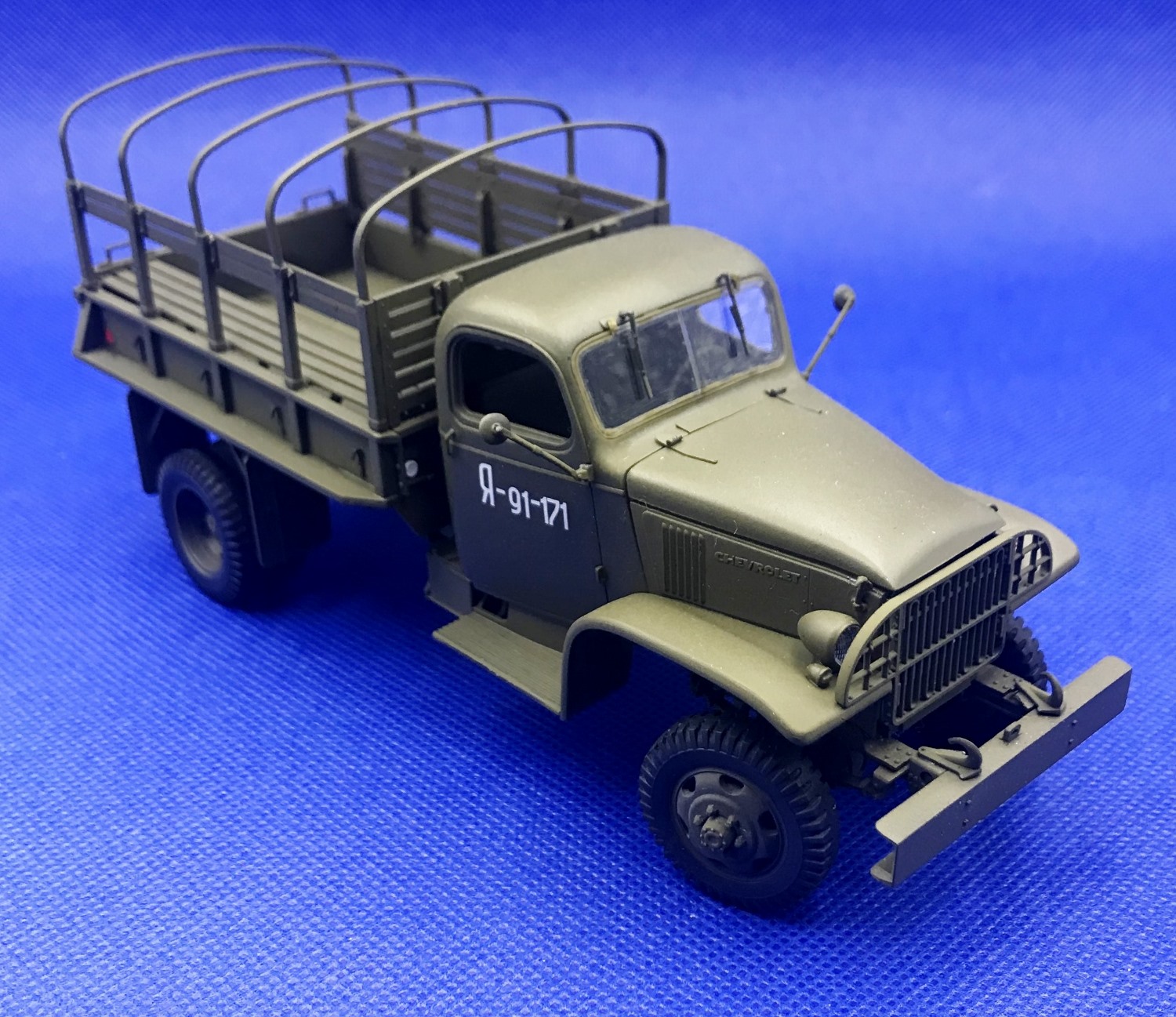
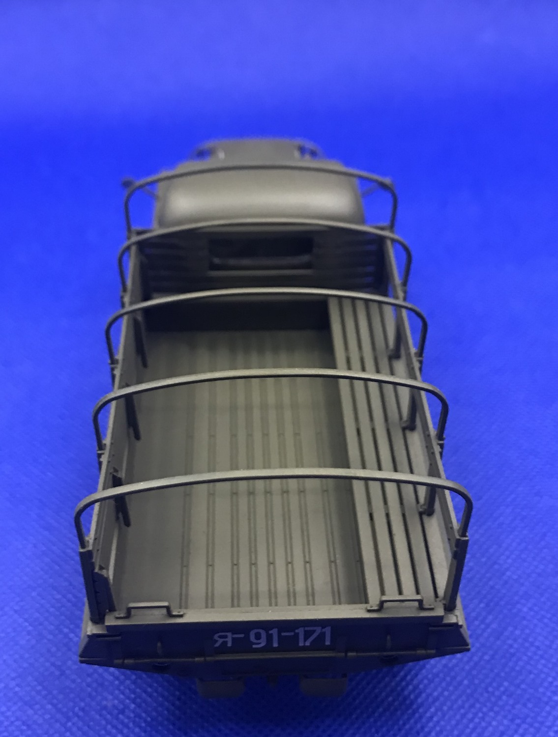
Steps 75-99: Moving onto the third and final subassembly stage is the construction of the cargo bed. Consisting of multiple parts, the steel bed has excellent detail. The side bed reflectors are either left on or removed depending upon which version is built. Step 96 shows the gas filler tube glued up from two parts (D28, D29) running through the front bed support B24. I chose to leave the filler support to install after the bed was glued on.
Steps 100-108: The wheels are constructed in these steps. They consist of two parts with a center hub. Tire tread detail is consistent with reference photos. Each part has reference points making gluing together a snap. A center hub is used to lock the wheels in place. Careful gluing on the hub allows the wheels to move.
Steps 109-116: ICM provides supports for the bed benches to be either deployed in the down or up positions. I chose to have one up and one deployed down. Excellent detail is molded onto the supports as well as the bench slats. Care should be exercised when removing the tarp bands (C7) in step 116. My suggestion would be to use as razor saw as I learned this the hard way. One of the supports snapped and had to be re-glued. ICM doesn’t provide a canvas cover, but one can be made easily.
Steps 117-129 consist of the final assemblies of small parts such as headlights, blackout lights, door handles, hood latches, and windshield arms. Whether the model’s windshield is to be displayed in the closed or upright positions, ICM provides wipers for either version. The mirrors, having the upper door hinge molded on, are glued in place. Part D6 (hinge) replaces one of the mirrors if using one only.
With the completion of step 129 construction is complete and onto painting and applying decals. As I had painted the sub-assemblies along the way, final painting was a snap, but I have included my process for painting below.
Painting and Decals
The chassis and wheels were primed with Ammo Mig One Shot Black Primer then two thin applications of ICM 1071 Camouflage Green were applied. ICM paints must be thinned 40-60% with distilled water or acrylic thinner. I used distilled water at 50%. The engine was primed first then one airbrush application of ICM 1025 Natural Steel was added. Weathering was applied using engine grime and dust washes.
The bench seat called for ICM 1009 Deep Green. Not having this color, I chose Vallejo Model Color US Dark Green 70.893 which had similar tones. A burnt umber wash was applied to bring out the seat details. The cab and cargo bed were primed with black primer and then two light coats of ICM 1009 Deep Green were then applied.
The tires were toned down to replicate the appearance of true to life tire colors by using light and dark slate grey pigments, and a pigment binder.
After an application of clear gloss acrylic, the decals were applied using Microset as the setting solution. They laid down as expected without any appearance of silvering. Located on the decal sheet are 3 red reflector lenses to use on the truck bed. However, I chose to use Tamiya X-27 clear red instead.
In Conclusion
Some parts are thin and delicate so the upmost care should be exercised when removing the parts from the sprues. ICM has laid out the construction in 3 major sub-assemblies over 129 steps with most steps involving 1-2 parts. The kit went together without any major issues. Since the Chevrolet G506 was used for the basis for different variations throughout the war, this kit makes a good starting platform. for constructing other versions of the 1-1/2-ton 4 x 4 such as radio truck, telephone truck, bomb service truck among others. My only complaint is that there were no Allied army markings included on the deal sheet.
After completing each kit, I ask myself, “would I build this kit again?” In regards to this kit, my answer is “most certainly yes. This definitely was an enjoyable build and I highly recommend it.
References used for this build and review include:
- Franz, Michael. U.S. WW II CHEVROLET 1 1/2-TON 4X4 Cargo Trucks, m6 Bomb Service TRUCK & Other Variants. Verlag Jochen Vollert - Tankograd Publishing, 2017.
- Andres, Didier. U.S. Army Chevrolet Trucks in World War II: 1 1/2-Ton, 4x4. Casemate, 2020.
- 1945 - 1946 Chevrolet Trucks 1-1/2 Ton 4 x 4 (1943 - 1945 Military Trucks), https://chevy.oldcarmanualproject.com/military/1945_46/index.htm.
- Washington, D.C.: War Dept. (1943, December 30). TM 9-805 1 1/2-ton truck, 4x4, (Chevrolet), 1943: United States. war department: https://archive.org/details/TM9-805/page/n245/mode/2up.
Thanks to IPMS/USA and ICM for allowing me to review this kit.


Reviewer Bio
Phillip Cavender

Phil Cavender, IPMS/USA #50085, is a retired pharmacist from the Veterans Administration, having retired in 2011. While he explored model car building as a child, it wasn’t until 2015 that he rediscovered plastic scale modeling. His renewed interest emerged while researching his father’s military history, which led him to a local hobby shop. There, he met a former UK military tanker who reignited his passion for the hobby. After relocating to Myrtle Beach, Phil teamed up with six skilled modelers to co-found the Grand Strand Scale Modelers chapter of IPMS/USA. He now focuses on building armor models in scales from 1/35th to 1/16th.
Comments
engine painting
The Chevy BV1001 235 engine was painted medium Gray (almost the colour of the plastic).
One problem I had was the steering connecting rod broke. I tried to re-glue a couple times, but would not stay together. Finally bent a brass rod and drilled the ends to accept this. It works, though still not happy.
Add new comment
This site is protected by reCAPTCHA and the Google Privacy Policy and Terms of Service apply.
Similar Reviews