
‘Buffalo’ 6x6 MPCV w/Slat Armor & Spaced Armor
This is the third version of the Buffalo 6x6 MPCV to be issued by Bronco Models. This release includes a different armor configuration than the previous two releases, with slat armor and spaced armor. This is an excellent kit that will be a challenging build for even more advanced modelers. The kit has lots of small parts, finicky assembly of the slat armor, but will result in a highly detailed and rewarding model.
The previous releases were reviewed here:
- Buffalo 6x6 MPCV, 2004-2006 Production, Chris Graeter, IPMS# 39558
- MPCV Buffalo with Bar Armor, Al LaFleche IPMS# 30337
From Bronco’s website & Wikipedia:
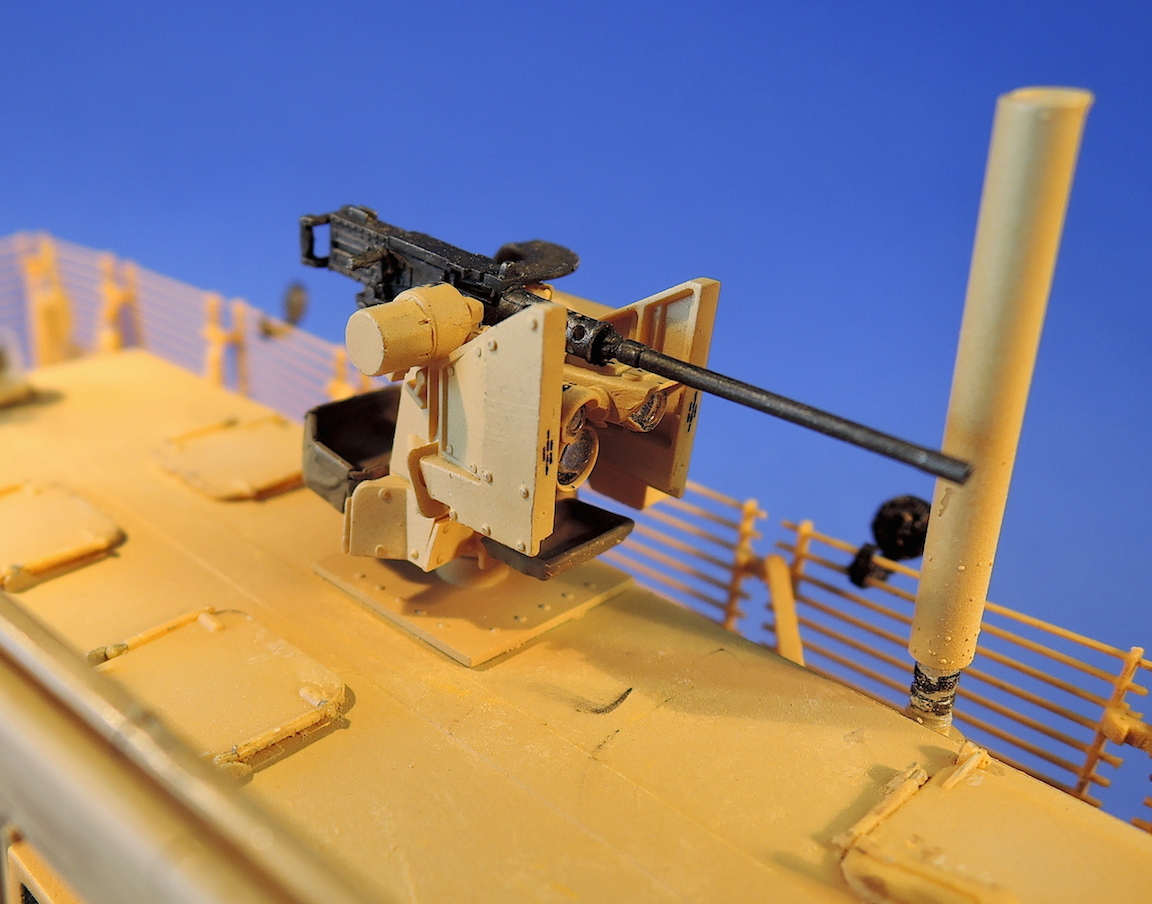
Force Protection, Inc. builds the Buffalo as a Class III Mine Resistant Ambush Protected (MRAP) armoured vehicle. It was based on the highly successful South African Casspir, but is larger and uses US 6x6 drive truck components. It features a “V” shaped hull to deflect mine blasts of up to 21kg of high explosive under any wheel. It also has an armoured body resistant to 7.62 NATO small arms ammunition. The Buffalo is intended for route clearance and has an articulated arm used to check the ground for mines and IED’s. A CROWS II remote controlled weapon station is also provided so the crew does not have to leave the vehicle to fire their weapons. Over 200 Buffalos are used by the US Army, more used by the UK, France and Canada.
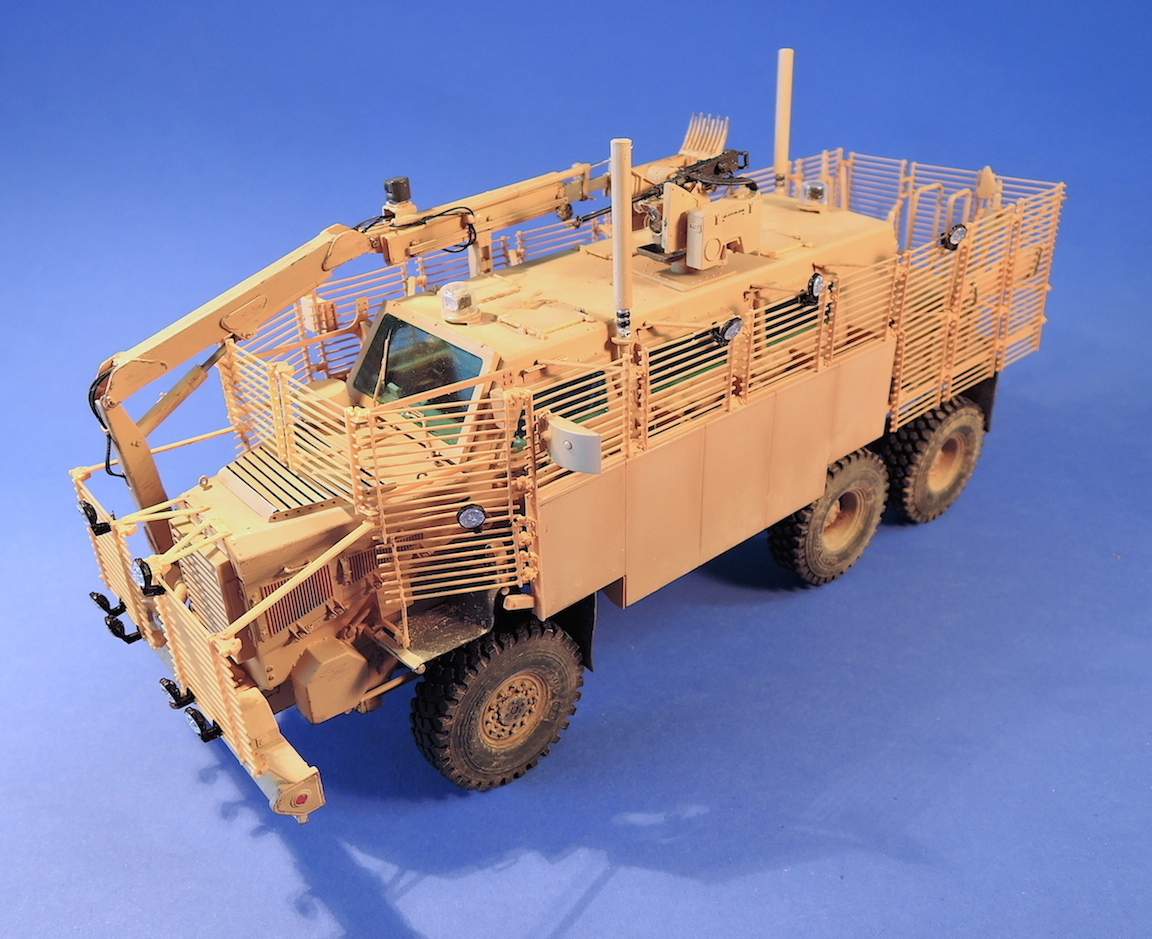
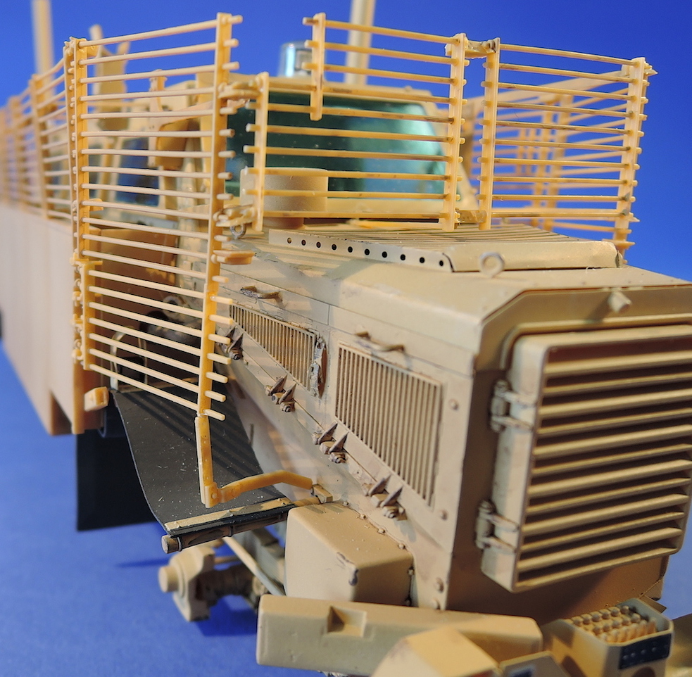
This kit has a combination of Slat Armour and Spaced Armour to protect against rocket propelled grenades (RPG) and anti-tank (HEAT) projectiles. The slats effectively break up RPG warheads before they hit the vehicle. The spaced armour protects against high explosive anti-tank (HEAT) projectiles, which create a focused jet of plasticized metal. This light armour detonates the warhead prematurely so that the jet of metal is focused well before the main armour, becoming relatively ineffective.
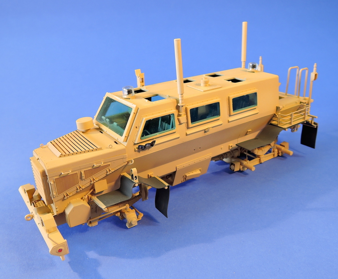
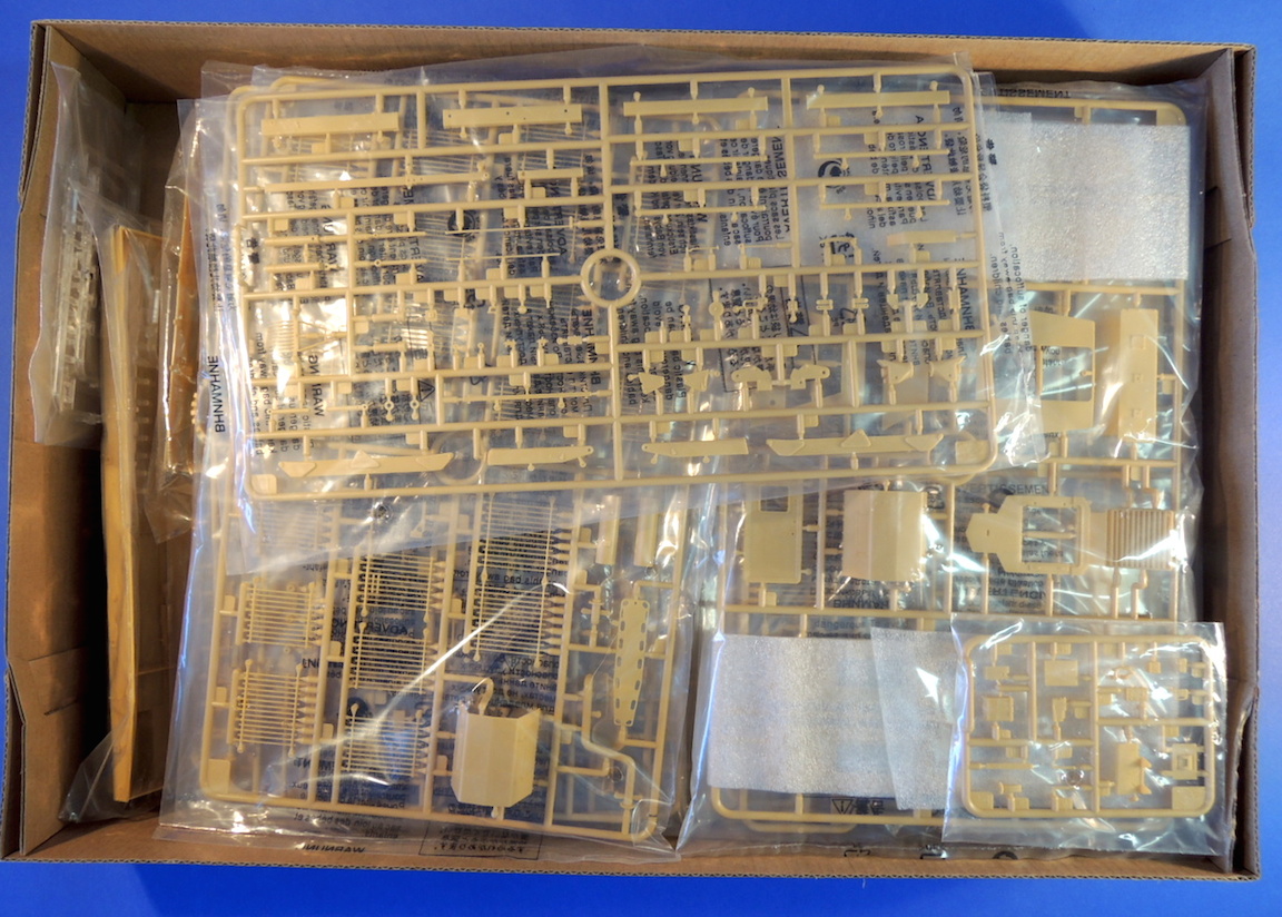
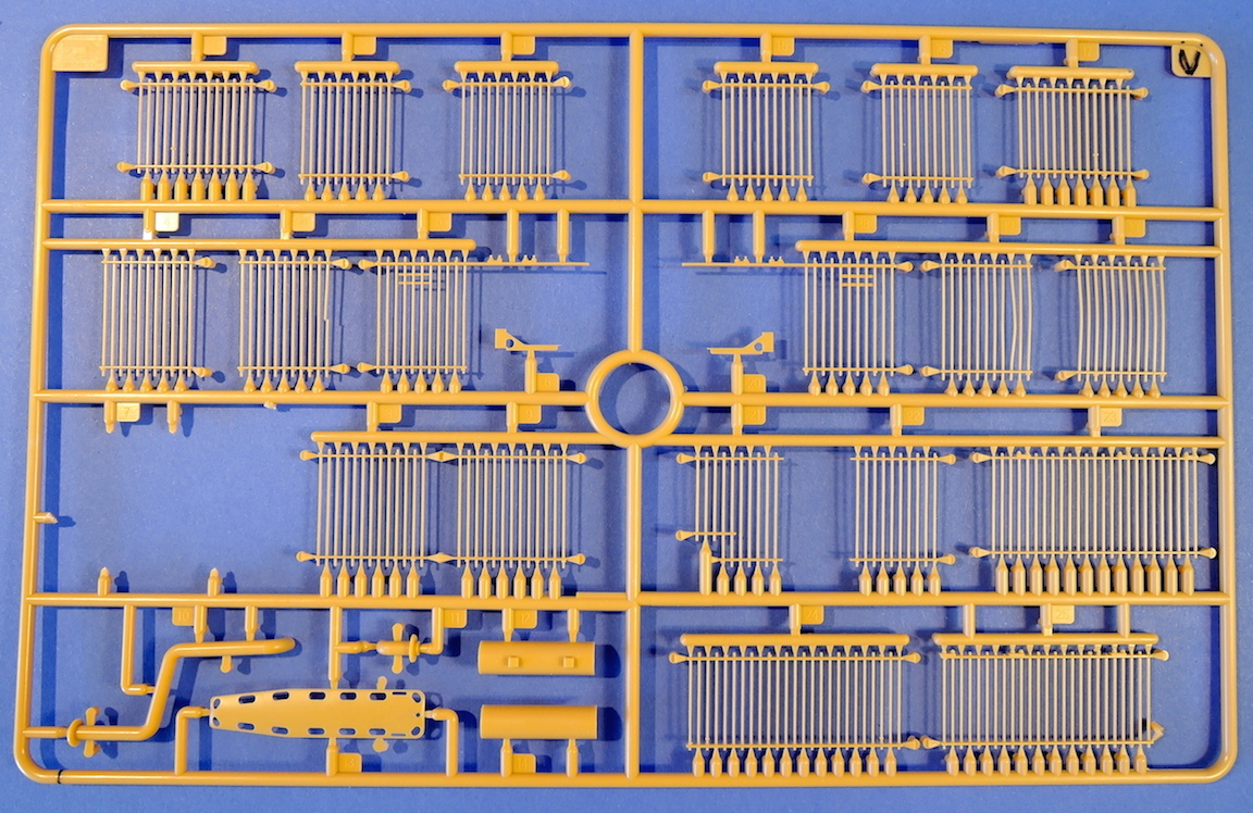
Opening the large 18x12x3 in. box yields an eruption of 20 light tan plastic sprues, 6 clear plastic sprues, photoetch fret, a small decal sheet, and some thin vinyl tubing for hoses. The sprues are bagged separately and seem well protected. The lower tub of the vehicle is nicely molded in one piece. The tire treads have internal sprues to avoid damaging the face of the treads, and are loosely packed in the box. After assembly the box is still full of partially empty sprues with lots of spare parts. The plastic parts are crisply molded with virtually no flash
The basic vehicle was assembled following Al LaFleche’s excellent review of the second release, the MPCV Buffalo with Bar Armor. Check Al’s review for notes on assembly of the base vehicle up through the installation of the mounting arm in step 43.
In this version of the kit, installation of the armor starts in step 44 with some plastic and photoetch brackets. I had completed and painted the basic vehicle up to this point as I assumed they would not be accessible after all of the armor is installed. Be careful to align the photoetch brackets with the appropriate bolts on the window frames.
Step 45 assembles the first spaced armor. The parts fit nicely, with location of the brackets in slots and the ridges on part J6. It was a bit of a struggle to get the exhaust pipe to fit when installing the right spaced armor in step 48. The exhaust pipe can be slipped into place after the spaced armor is installed, but it was a tight fit between the muffler and mounting hole in the hood.
Step 49 assembles the lights on the slat armor consisting of a photoetch bracket, plastic light housing, and clear plastic lens. There is also a bolt that can be cut off of the sprue and attached to the back of the photoetch bracket. For the sake of sanity I skipped installation of the bolt heads – too small, difficult to glue, limited impact. There are two options for the light assemblies, depending upon whether the photoetch bracket is folded down. There is no explanation of the different applications of the two bracket configurations. Step 50 assembles many of the light assemblies to the slat armor pieces, but I am held off fastening them until assembly was complete so they wouldn't break off. This was a bad idea as I found out later how difficult it was to install the light brackets on the slats. I think it would be better to install them as the instructions call out at this step. It’s still very difficult to slip the brackets through the slats, hook them on the slat able, than bend down the tab. I never was able to bend down the tabs and simply super-glued the brackets in place.
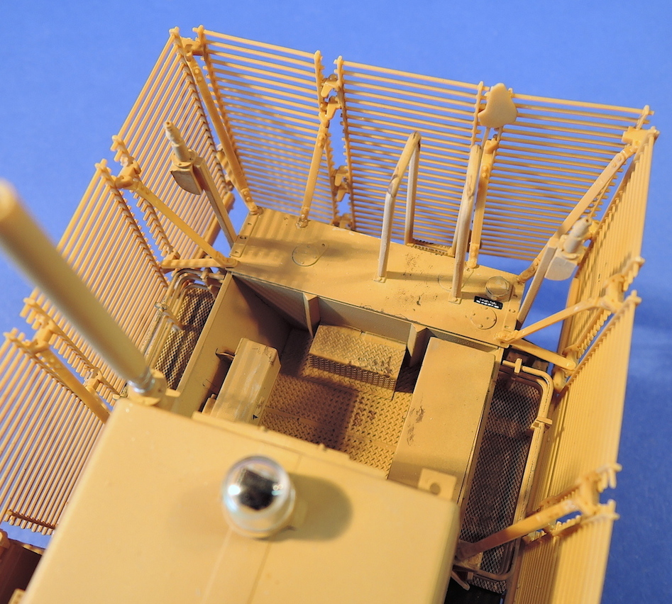
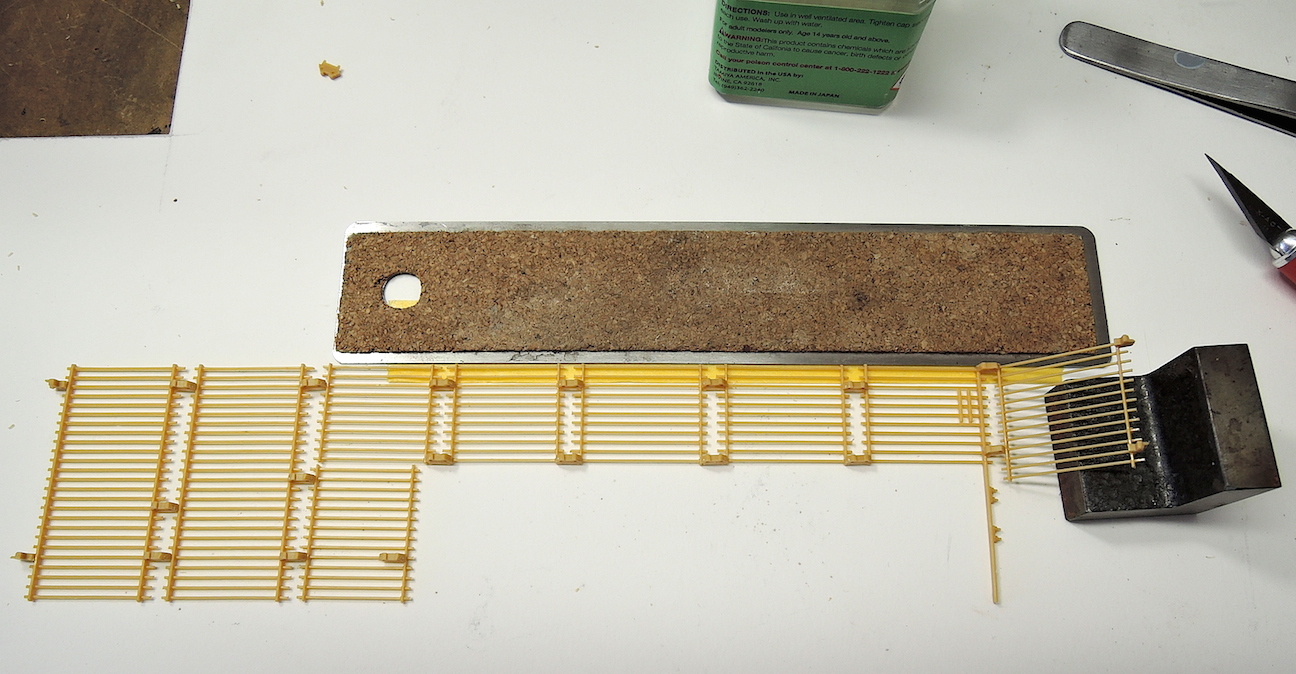
Assembly of the left side slat armor panels begins with the step 51. There are 10 panels that make up the left side armor, and they are all finely molded. The panels do have a top-bottom, left-right orientation. The best way to get the panels in the correct orientation is to find the lugs where the connecting brackets attach and get them in the correct up-down, inside-outside orientation. The different panel connectors give the correct orientation by closely observing the instructions and seeing how the connectors attach to the slat armor panels. The connectors M8 will give the correct angle for the end panel V8. The four attachment brackets are all at different angles to the sled armor. I plan to glue these brackets to the slat armor just before installing the panels to the vehicle body to allow adjustment for the correct angles.
There is lots of opportunity for variability in the size of the left and right panels based on how they are glued to the connectors. It would have helped to have a template or some other means to accurately determine the overall length of the side panels. As it turned out later, my side panels were either located too far to the rear or were too long.
After assembling the left side panel I decided to finish the painting, decal application, and slight weathering of the body. This will all be difficult to reach once the slat armor panels are installed.
There are only a few decals provided by Bronco, mostly warning labels. The decals add nice detail to the vehicle. The decals are quite thin and the decal film is kept close to the image.
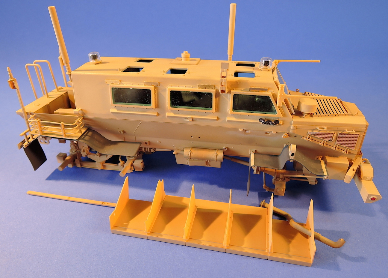
The vehicle was painted with Vallejo Model Air Light Brown, with the center of the panels highlighted with Vallejo Model Air Sand (Ivory). Vallejo Panzer Aces Dark Rubber was used for the tires and mud flaps. Some of the lower areas of the model were filtered with Sin Industries Grey for Dark Yellow to darken up the light brown color slightly. Vallejo Panzer Aces Track Primer was used for some very minor chipping. The vehicle would've been fairly new so chipping and wear was kept to a minimum. MIG Productions Brown Wash was applied to the sides of the vehicle and spaced armor, and MIG Oil and Grease Stain Mixture was used on the undercarriage drivetrain and articulated arm. Windows were tinted with Alclad Armored Glass. The final step was a light dusting of MIG’s Gulf War Sand pigment.
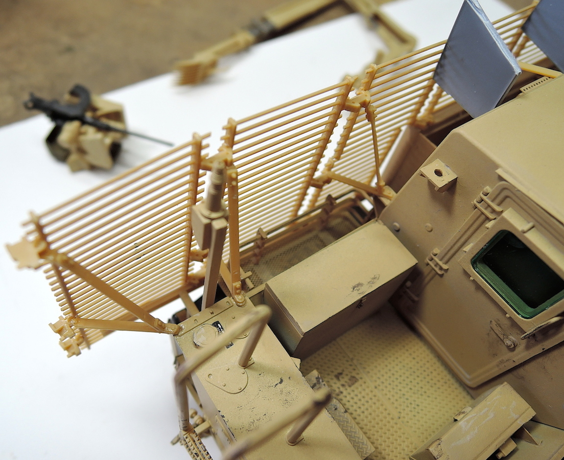
Steps 51 through 55 install the left and right side/armor assemblies to the vehicle. In step 54 the upper connector between parts V9 and V5 is not labeled but should be bracket M9. I glued the brackets just before installing the slat armor assembly so they could be adjusted to the correct angle. I found it easiest to locate the front-back location of the panels using the vertical bracket in panels V18 and V5. The M11 brackets were then cemented to the top of the spaced armor. Getting the front to back location of the side panels is critical for alignment of the front panels and rear panels later on. The front hinged panels, parts M34, were installed after the rest of the slat armor panels were fastened to the body. Part Y4, the bracket for this hinged panel, is a flimsy butt joint to the underside of the panel, and lies on top of the mud flap before been anchored to the body.
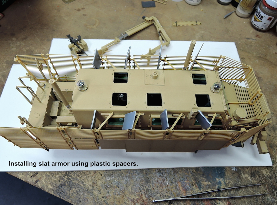
Step 56 installs the slat panels in front of the windshield and braces for the side slat panels. I needed to loosen the front brackets for the side panels to spread them out enough to get the front slat panel in place. I am also needed to use the plastic shims to move out the top of the side panels.
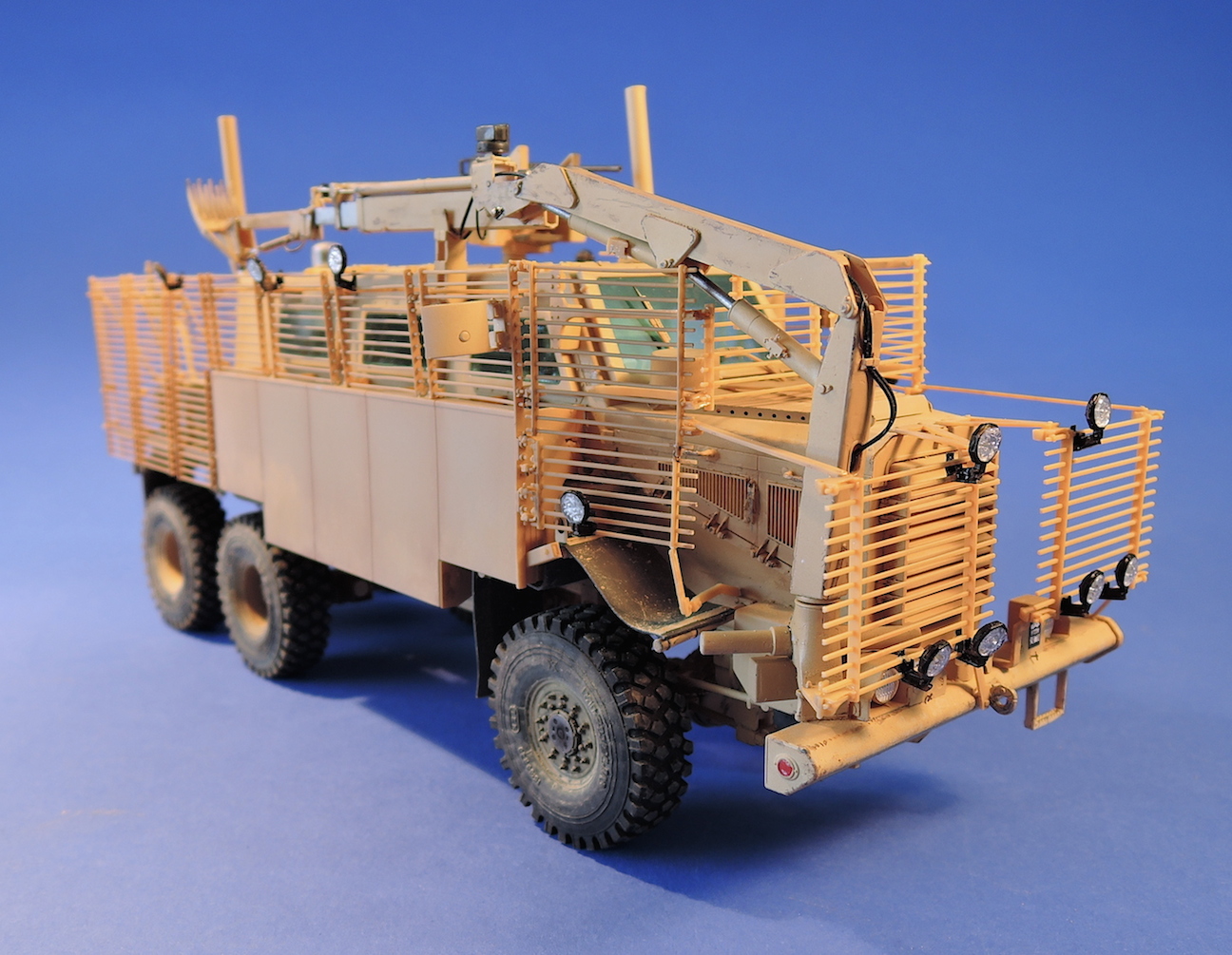
Step 57 and 58 assembles and installs the slab panels and gate on the rear the vehicle. Both of the side panels on my kit were too far to the rear of the rear panels and so the gate bowed in towards the center.
The spaced armor installed easily, but the slat armor was a challenge. Getting the right spacing between the panels, and accurately locating the panels on the vehicle is critical, but not well defined in the kit. Some minor warping of the slat pieces also contributed to a wavy appearance of the armor on the vehicle.
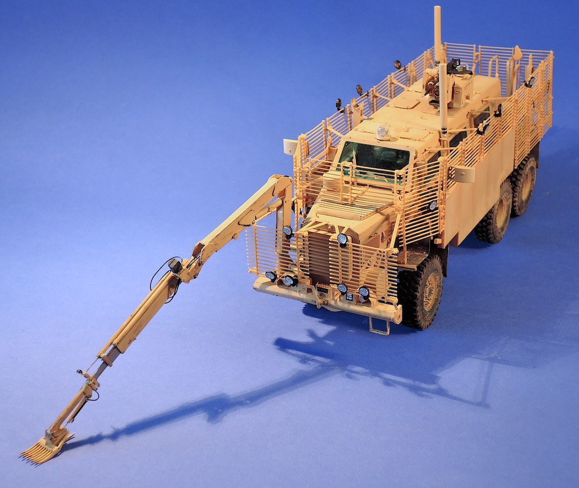
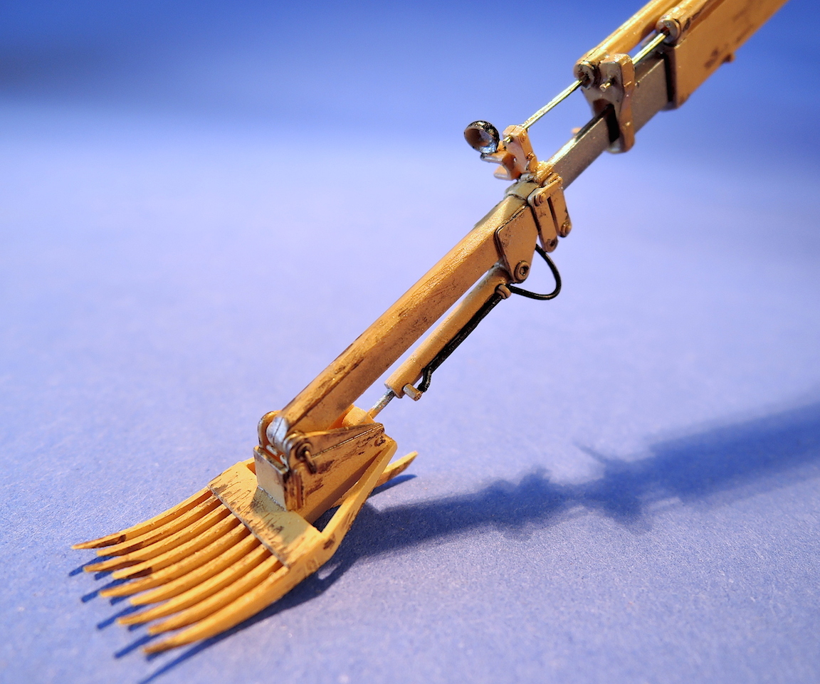
Step 51 installs the hydraulic cables on the articulated digger arm and fastens it to the front of the vehicle. There are additional runs of hydraulic lines shown in reference photos. Step 60 shows the digger arm in the folded, stored location. Mine ended up being a little off-center from the opening in the front slat armor so they arm did not accurately line up with the storage bracket. Another alignment issue with the slat armor panels.
Steps 61 through 63 installed the remaining slat armor panels on the front of the vehicle.
At this point I installed the lights on the slat armor. This was too difficult at this point and should have been done before the panels are mounted on the vehicle, as the instructions call out.
The last assembly step was to install the wheels, using five-minute epoxy to allow time to square up the wheels.
With that the kit is done. This turned out to be a great kit of a very interesting Gulf War vehicle. The kit appears to be very accurate compared to the online reference photos. The kit is difficult, has lots of pieces, and requires careful alignment of the slat armor. This kit is not for less experienced modelers due to the number of parts and the finicky alignment of the slat armor panels. More advanced modelers will enjoy the challenge of the build and will end up with a very nicely detailed kit.
A special thanks to Dragon Models USA for supplying the review sample to IPMS. Thanks to Bronco for making this wonderful kid and to the IPMS review crew for letting me build it.


Comments
Add new comment
This site is protected by reCAPTCHA and the Google Privacy Policy and Terms of Service apply.
Similar Reviews