
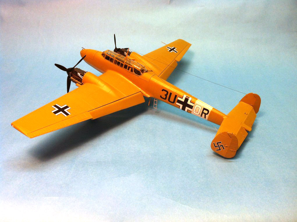
Bf-110E-2
Are you familiar with Japanese Puzzle boxes, sometimes called “trick boxes” or “secret boxes”? A Puzzle box is a box that can only be opened through some “obscure or complicated series of manipulations”. The boxes contain a good luck charm and are designed to trick or confuse the person attempting to open them. Some require only a handful of movements in order to slide the various parts of the box into an “open” configuration, and some require hundreds of manipulations. Indeed, Japanese Puzzle Boxes are known for their complex and challenging design but they are also known for their intricate geometric patterns and their exquisite engineering and construction.
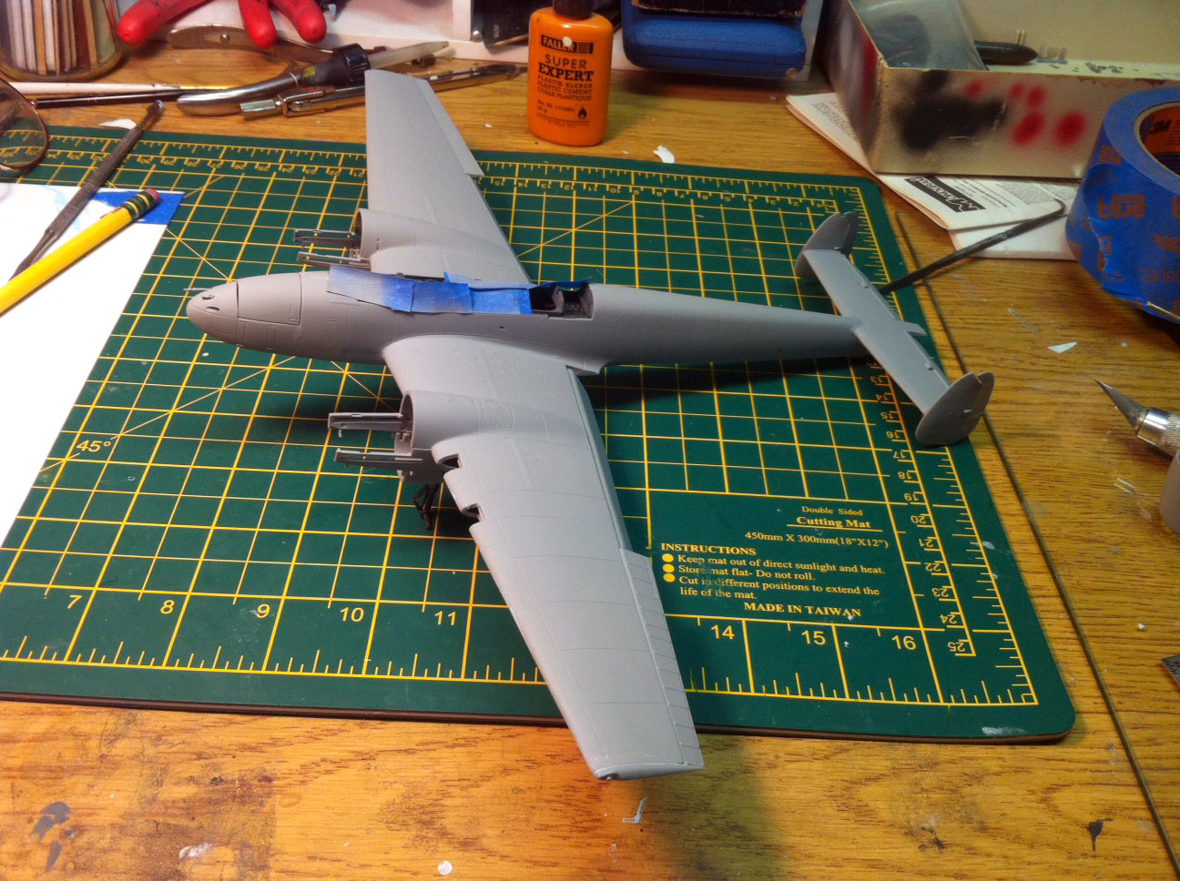
Dragon offers a “plastic model” version of the Puzzle Box in this Bf-110E-2 kit. The parts are exquisitely molded with virtually no flash and few mold release marks that will be visible once the model is complete. The kit features recessed panel lines that mark such features as access panels and maintenance hatches. The control surfaces have a slightly different texture than the airframe surfaces. The airframe is, of course, smooth as one would expect from a “metal” surface while the control surfaces have a slightly rougher texture that gives the appearance of a surface covered with fabric. Many of the parts are extremely small and require much care to successfully remove them from the parts carriers. In some cases it is advisable to put down the part nippers and pull out a micro-saw so that no torque is applied to the part when clipping its plastic umbilical.
So, is this model “designed to trick or confuse” the builder? Absolutely not. In fact, this model, although challenging for me, was a joy to build. The fit is amazing, the parts are molded at a high level of quality, and the entire product is superior in every way. This “plastic puzzle box” is an intricate and excellent display of the art of model manufacturing. When the modeler identifies and follows that sequence of construction steps that are the “handful of movements” discussed in the opening paragraph as opposed to the sequence that would lead to unnecessary manipulations, then the builder will find this model rewarding and extremely enjoyable. If, on the other hand, one does not study the instructions, think through the various assembly steps, and then assemble each sub-assembly with proper alignment, then one will find the model, at times, frustrating.
Be clear about it, this model is engineered with great precision, and is of excellent quality from first piece to last….but plan your approach to construction carefully.
The instruction sheet is a quad-fold “poster “with large and very clear illustrations divided into 10 construction steps, two decal and color scheme steps, one page which shows the 16 parts trees with pieces not used on the 110E-2 in blue highlight (not too be used in assembling the variant provided in the box), and ½ page dedicated to the ubiquitous color call-out chart which uses GSI Creos and Model Master paint. I found only one error on the instructions, that being in Step 1. A part is not identified with a number on the plans….it’s Part # F51, a large “box” that is attached to Part # F36 which is the cockpit floor. The unidentified part is shown to be attached to the rear right corner of the cockpit floor. Study the instructions carefully. This will help you to avoid attached a part in the wrong location or getting a part backwards. For example, in Step 9 one must select attaching the flaps at 90 degrees (in line with the wing surface, or retracted) or at 45 degrees. Studying the kit instructions one will see that there are some parts that should be attached if the flap position will expose a portion of the wing root. Knowing this little fact will save one from filling in that gap under the false impression that it is an imperfection on the design of the kit. In Step 8, studying the outline and shape of the 8 bulkheads that fit into the wheel well will help the builder to attach the bulkheads properly, rather than backwards. A very important sequence is the assembly of the landing gear, making sure that the parts are not swapped from left to right. I’d advise dry fitting the parts, or even going so far as to use small dots of Future floor wax to hold the parts in temporary position until one is sure that all is correct. Step 7 will be your guide in regard to the gear.
The part trees are numbered in sequence! No random searches for a specific part or part #. L2 is next to L3 which is next to L4, and so on. It’s a little thing but it makes finding a specific part very, very easy.
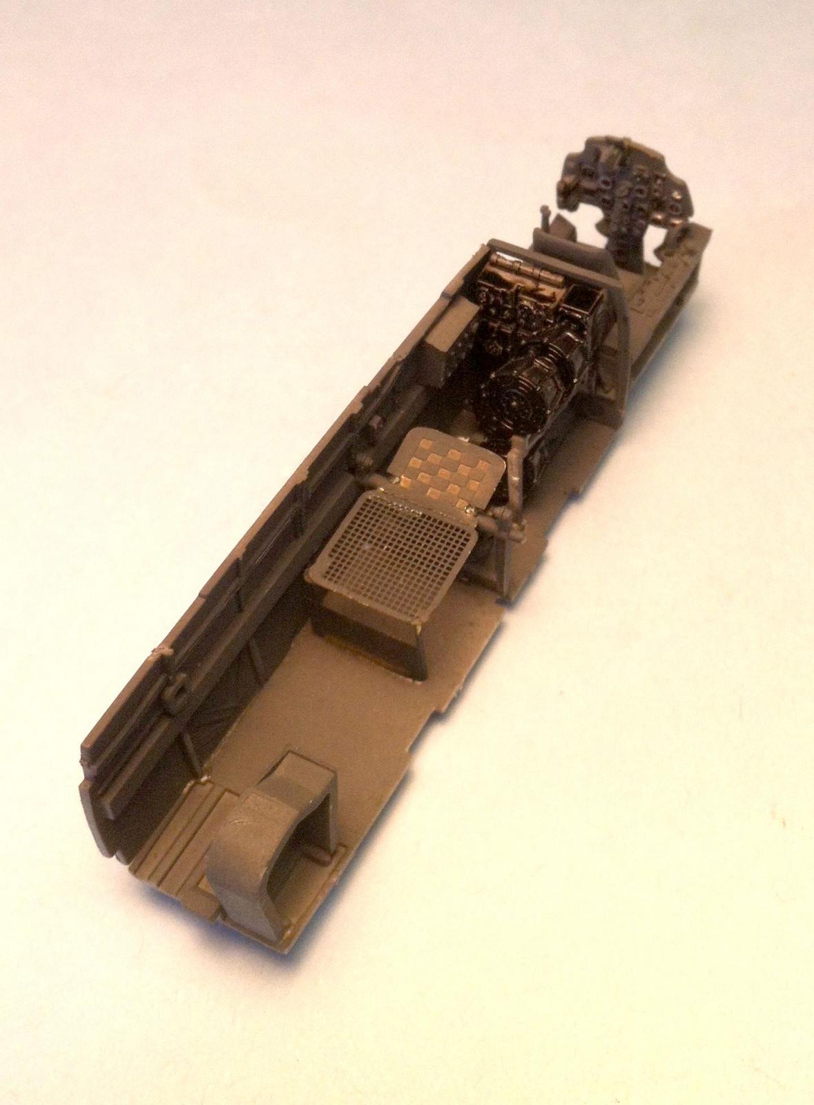
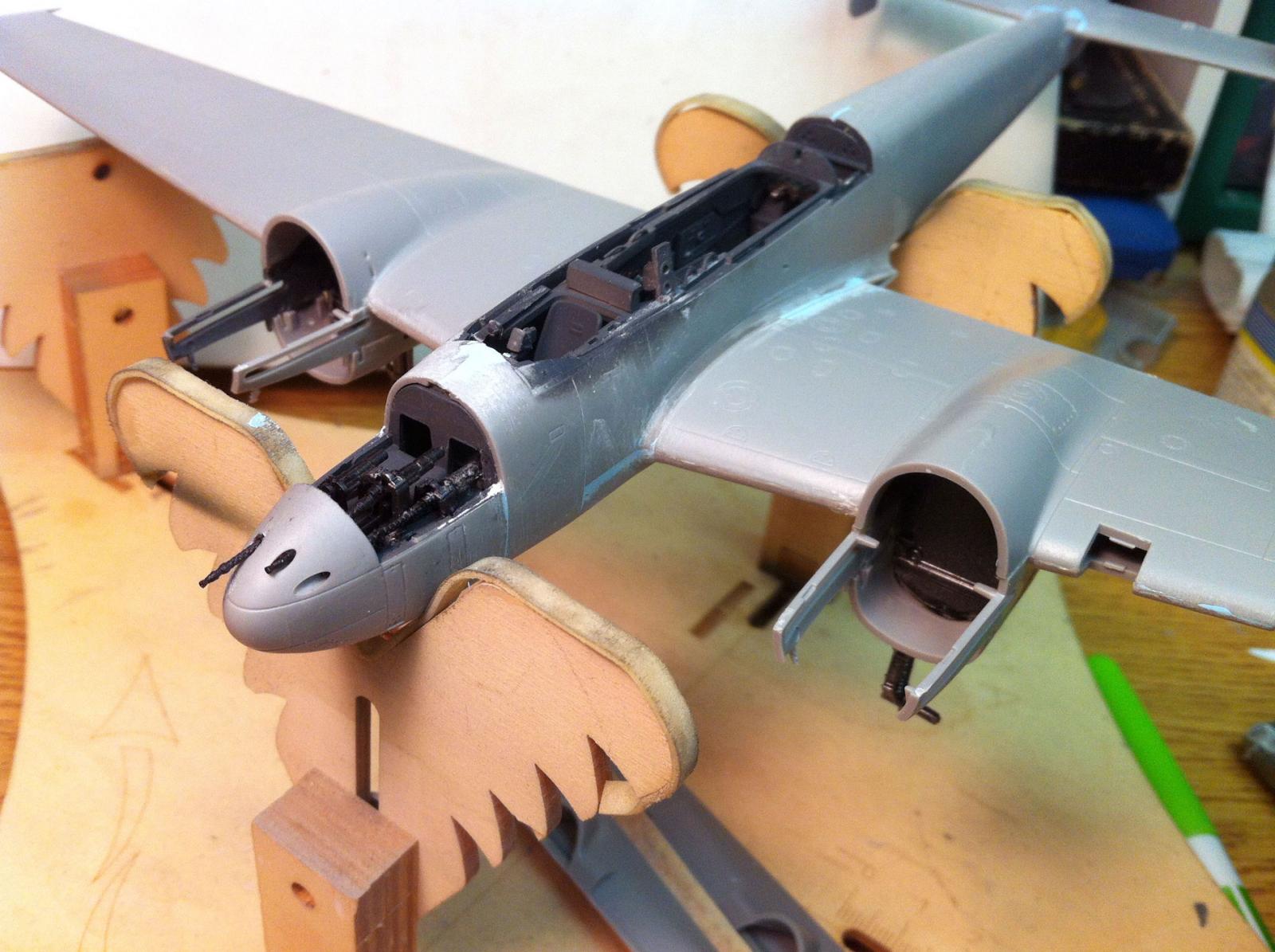
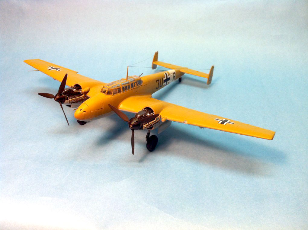
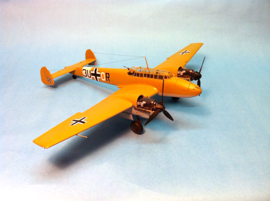
The parts are molded in a light gray color and there are 16 part trees, two part trees of clear parts and one PE fret. This kit provides a cockpit packed with detail, some very remarkable engines, control surfaces that can be positioned, and optional bomb loads and external fuel tanks. There are options that allow for various internal areas to be displayed such as the engines and the ventral gun bay.
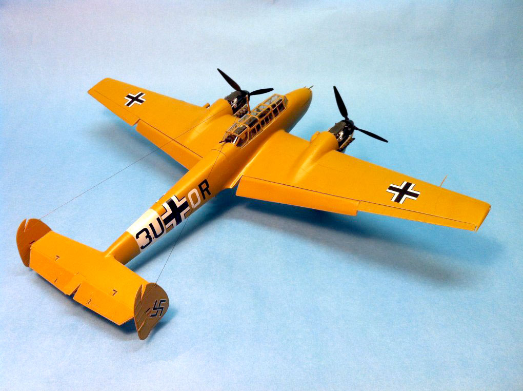
There are two canopies in the kit. One canopy is a single piece with all the hatches closed. The other canopy consists of eight pieces with hatches that can be positioned as “open” or “closed”.
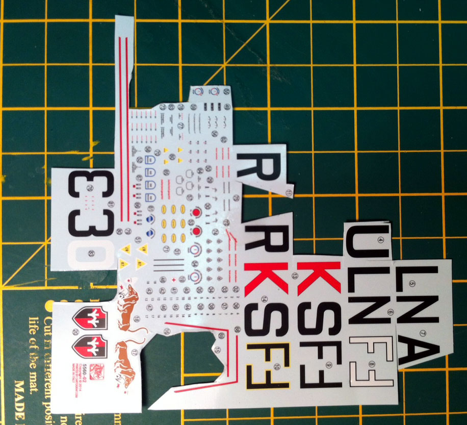
One small decal sheet is included, only 4 ½ inches square, but jam packed with national and squadron markings along with many, many stencil decals. It should be noted that it is quite difficult to use scissors to remove some of the decals as the space between the individual decals printed on the sheet is very small. Get a clean cutting surface, grab a straight-edge and a new cutting blade and you’ll have no troubles. Of great importance is that the decals have very little backing material extending beyond the printed decals themselves. You will not have to remove the area between the uprights of the “U”’s , or the triangle within the “A”s. I found that about 20 to 25 seconds of soak-time in lukewarm water was all the markings needed. The markings were strong enough to allow for some repositioning once applied but thin enough to shrink into panel lines very nicely. In a few words, the decals included in this kit are excellent!
Do as much of the painting as possible prior to starting assembly. Be sure to paint the inner surfaces of the engine nacelle parts, including the interior surfaces of the wings as some of that area will be visible, depending on whether you open some hatches. And please open the hatches! The engines are just too exquisite to be hidden from view!
The decals include markings for 3 aircraft: 8/ZG 26, N.Africa, 1942; 7/ZG 26, Italy, 1941; and 7/ZG 26, Libya, 1942.
This model is recommended for those with some experience. The kit instructions do not suggest a sequence for construction per se, but rather which parts need to be glued together and which options are available to the builder. It is up to the builder to figure out how to open this particular “Japanese Puzzle Box” (getting parts and sub-assemblies together in a sequence which leads to successful construction). The quality of the molding, the detail, and the fit are exceptional.
Thanks to Dragon USA for supplying this Cyber Hobby kit to IPMS for review.

Comments
Add new comment
This site is protected by reCAPTCHA and the Google Privacy Policy and Terms of Service apply.
Similar Reviews