
Battleship USS Missouri BB-63, Part 3
This Report 3 covers the completion of the build from Steps 49 through 64.
As stated in the previous two reports, the fit of plastic parts was excellent. Issues encountered involved the handling and attachment of small plastic and thin PE parts, particularly where there is little if any gluing surface, and with lack of detail in the instructions. None of the issues are deal killers. Each can be handled if you are aware of them in advance and plan accordingly.
Parts and Photoetch Issues
Overall, the thinness of the PE caused some headaches, as it was easy to damage or bend some parts out of shape in the routine handling and cutting of the parts off the sheets.
Examples
- One of six of the stairs (PE-D3) came apart and a section of the railing (Part PE-B26) came apart when bending (Step 55). I carefully retrieved the three rail pieces of PE-B26 and glued them on as best I could (Photo 28). Avoid using a sharp blade edge to make the bends. Plastic single-edge tools shaped like razor blades or the plastic straightedges that come with the Etchmate 3C PE bending tool are what I found to be best to avoid breakage.
- Before you do anything, slowly peel away the clear plastic from both sides of the two “C” PE sheets, carefully cut off the four Parts PE-C52, and store them safely until they are attached to the access stairways in Step 63. They are the most delicate of the PE parts. It was my fault that I damaged and thus lost three of the four of them without even realizing it and had to leave them off the build.
- The four access stairways to the ship, Parts PE-C30 have a weak upper railing that needs to be bent 90 degrees into position. It is easily broken off if stressed while bending.
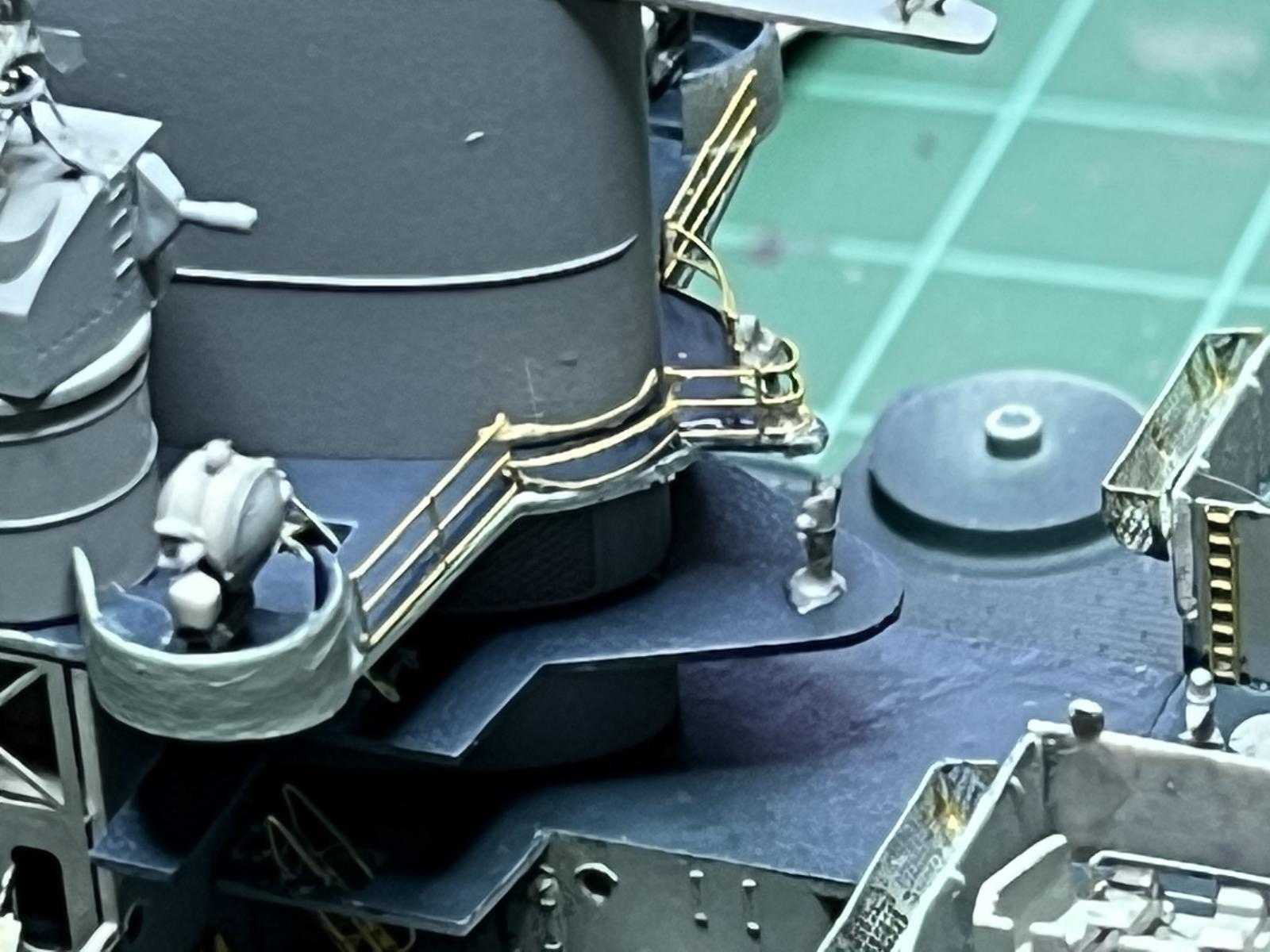
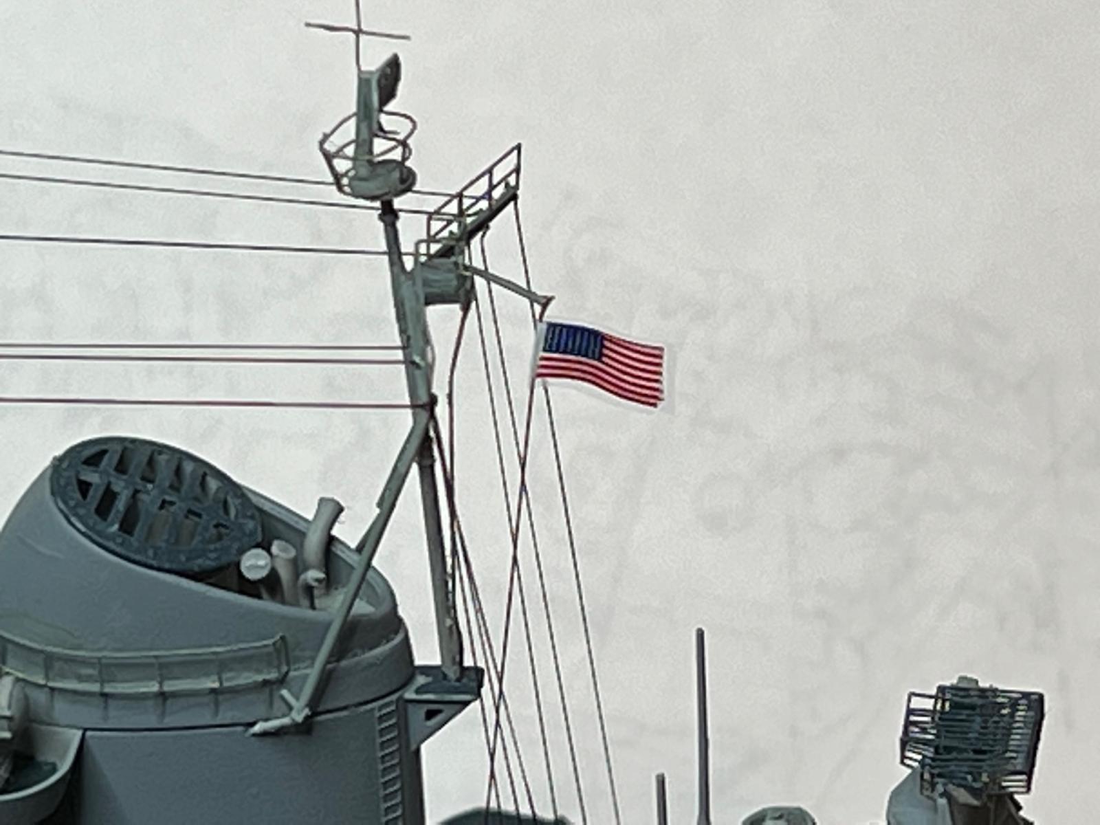
- There are two cross-shaped PE antennas located at high points above the two stacks. These are so thin that after installation they are almost invisible in normal lighting and are subject to inadvertent bending and/or breakage if you are not careful. Trust me on this (Photo 29).
- I found that Parts L41, the supports of the two lifeboats, were frail. My own ham-handedness broke one that I needed to repair. Also, for me, the assembly of the two pieces of the two hoists for each boat, four each of Parts K27 and 37, was unclear, and the miniscule photoetch hooks, Parts PE-C21, were difficult to get onto each hoist. On the starboard side I tried putting the hoists on first, then the boat. On the port side I put the boat on first then the hoists. I must have been having a bad day as neither procedure worked satisfactorily. I ended up jury rigging both boats and their lifts into place.
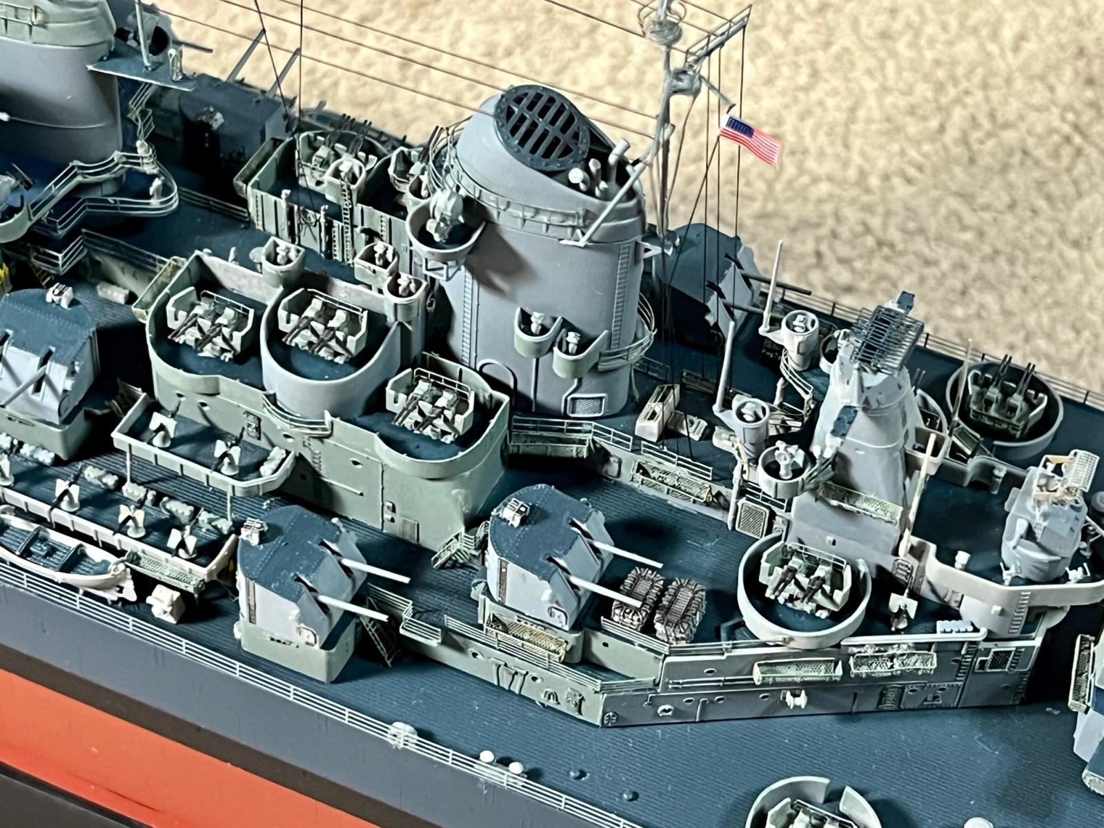
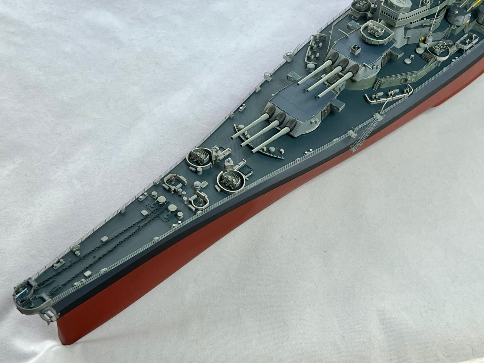
- What appear to be kickplates, Parts PE-D2, -C11, and -C31 along the edges of the three main turrets (Step 60), are very thin and have very little gluing surface (Photo 30). As such, they are difficult to get attached in a vertical position. In my opinion, there would be very little, if any, detail lost if these features were molded on the turrets (Parts K43).
Instruction Issues
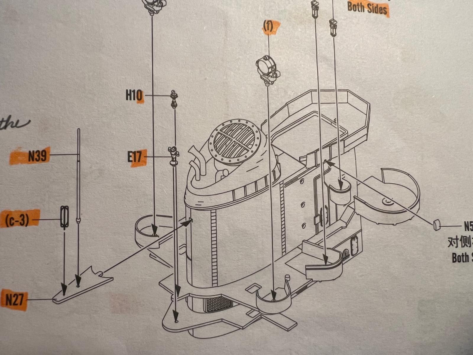
- Instructions call for cutting and removing a piece of Parts E2 and E4 after they are glued together in Step 51 (Photo 31). The exact shape, size and location of the cutout are not specified. The cut is apparently for Part N27 that is installed in Step 52 (Photo 32). Check Step 52 ahead of making what amounts to a small rectangular hole. I also decided to attach Part N39 and assembly c-3 to N27 before cutting N27 off the sprue to make a subassembly that makes it easier than gluing the parts separately to the stack (Photo 33).
- The main deck railings are installed at the very last step of the build, after all other parts are in place. However, certain installed parts interfere with attaching the long port- and starboard-side rails at the bow of the ship, Parts PE-A7 and -A5 respectively. I could find no clue about any options or workarounds for this in the instructions. These interferences are caused by D-shaped Parts L1, L2 and M1, installed at the edge of the hull, per the instructions in Steps 11 and 14, and by two U-shaped, railed-in platforms, Parts PE-C48 installed in Step 19, that overhang the edge of the hull on both sides of the bow. These platforms are in the way of the railing (Photo 34). The modeler is forced to consider either leaving the platforms off or cutting out a section of the rail in which to fit the platform. After removing all four Parts L1 and L2, and 20 Parts M1, and regluing them a fraction of a millimeter away from the hull’s edge, I removed the PE-C48 platforms, installed the long railings as diagrammed in Step 64, then cut a section out of the railings, added posts of flattened telephone wire to the ends where the cut was made, and glued the platforms back on. (Photo 35).
- Note: In an attempt to get info regarding the railing interferences, I found a WWII photo of the USS Missouri that showed the main deck railings inside of what appear to be model Parts L1, L2 and M1. Positioning the railings per that WWII photo conflicts with the kit instructions, which indicate that the railings are to be placed at the edge of the main deck. Whether right or wrong, and considering that the railings could not be placed on the model inside of Parts L1, L2 and M1 without major cutting and sectioning due to the interference of walls around gun emplacements as well as the L1, L2 and M1 parts themselves, I decided to install them as described above.
- There are no instructions for attaching the two aircraft to the catapults. I drilled a hole in the underside of the fuselages and glued in a pin to fit into one of the two holes in the catapult plates, Parts L13, that carry the planes. I glued the aircraft to the catapults at the end of the build.
Regarding the instructions in general, they may be adequate for experienced ship modelers but leave something to be desired for more novice builders. Most of today’s kit instructions are pictorial only and many lack detail. In my opinion, as mentioned in Report #2, today’s kit manufacturers would better serve less experienced modelers by providing instructions that were pictorial with descriptive text for each assembly step, or like those that had marginal details of subassemblies in addition to and alongside the main diagrams. The latter are extremely helpful when dealing with complicated assemblies. The sprue diagrams in this kit’s instructions have part numbers that are so small you need a magnifier to read them. And as mentioned above, I found it hard to ascertain how Parts K27 and 37 attached to each other. I jerry-rigged them, but a less experienced builder might get frustrated in trying to put those pieces together.
In addition to improving detail and clarity, I’d make two recommendations for this kit:
- Provide bend diagrams.
Simple line diagrams showing how the odd-shaped railings should be bent, i.e., plan views of the shaped railings printed to scale that could be used by the modeler to shape the photoetch parts exactly as required prior to attachment. These plan lines could be placed at the assembly step or grouped on an up-front page associated with the sprue diagrams. They would save time and minimize inaccuracies. - Provide rigging instructions.
There are no instructions for rigging, which is bewildering given the extensive level of detail in this kit. The modeler needs to search the internet or historic photos of the Missouri to determine the rigging arrangement in the time frame that the model depicts, in this case 1944-45, as it varied over the life of the ship. I located the instructions of a 38-year-old kit that had a rigging diagram option for this period, and I rigged this build accordingly using fine grade E-Z Line.
Miscellaneous Minor Items
- Part PE-C25 is not marked on the two “C” photoetch sheets. It is located between #24 and #26.
- The main radar dish, Part N20, is solid plastic with embossed ribbing. PE-E7, a series of concentric rings, is to be separated from its PE sheet and the rings installed individually inside the dish as additional detailing. While adequate, it is surprising, given the fine detail and extensive number of plastic and photoetch parts provided in the kit, that this radar dish is not provided as an open-structured type screen either in photoetch or plastic (Photo 36).
- PE-A10 not marked on the “A” sheet. Confirm it by process of elimination.
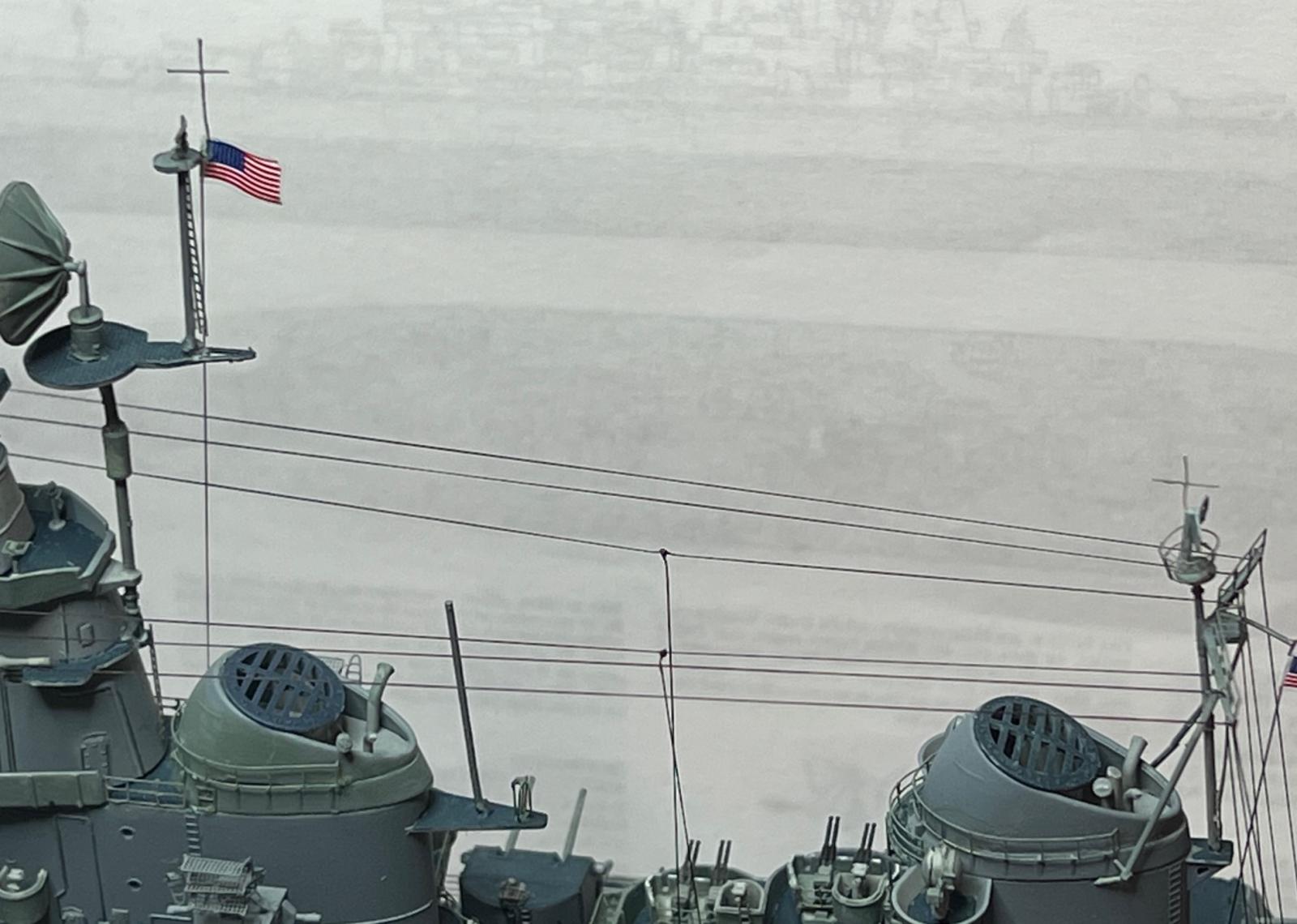
- If rigging the model, a rigging line to which the second flag is attached to the rear mast needs to be far enough away from the mast to avoid contact with the platform to which the mast is attached. I added an extension made of plastic strip, akin to the part in the 1985 kit rigging instructions referenced above, to attach the flag line and avoid any interference (Photo 37).
Since there are multiples of sprues K, L and M, there are a few extra parts left over, such as life rafts and plastic gun barrels. Sprues D, E, F, G, H, J, N, P and SC-1 are completely used. There are also some extra ladder, railing, and stairs on the PE sheets, so even though I lost a couple to breakage, I had more than needed.
Summation
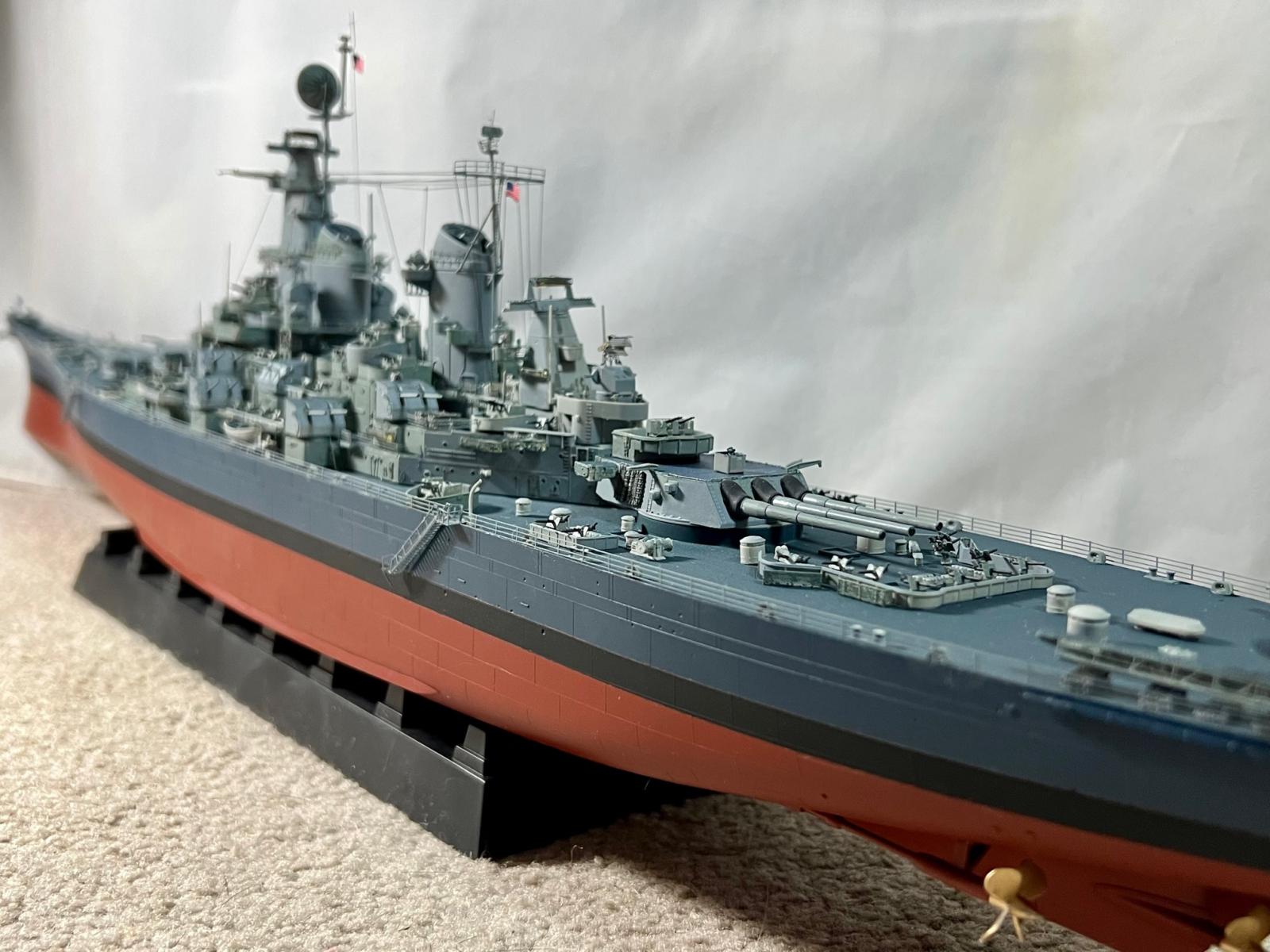
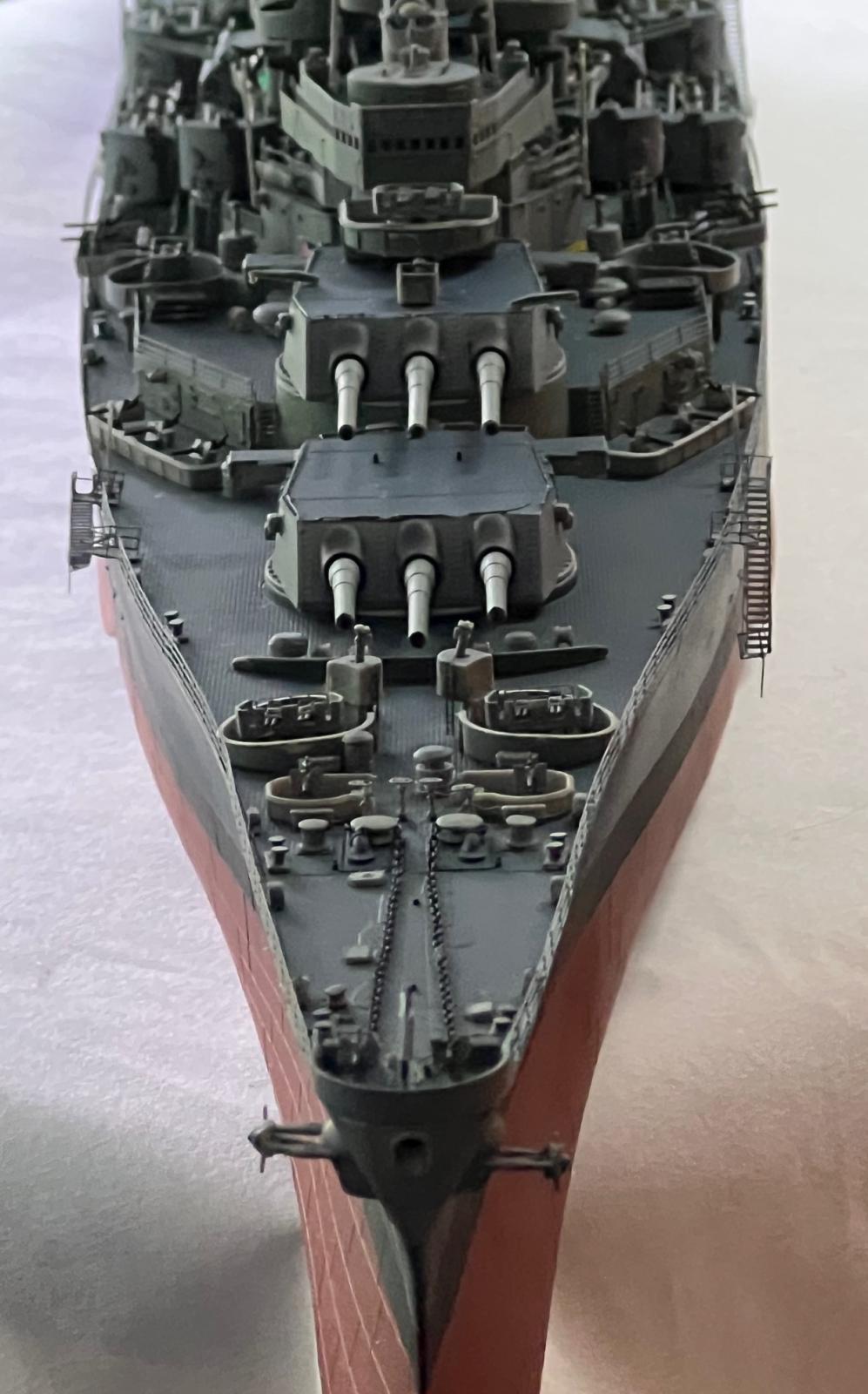
This may not be a model for a novice but it’s a terrific kit for an experienced shipbuilder. Overall, I spent about 300 hours over a period of two months working on the kit and the review reports. I would guess that an experienced shipbuilder would take less time unless they were building for a contest. In spite of the issues mentioned above and in the previous reports, which can be satisfactorily addressed with time and patience (and reading these reports before you start), I am extremely pleased with the result. See Photos 38 through 47. I have ordered a custom display case for this model and am now inspired to get into building a few more ships.
I want to express my sincere thanks and appreciation to Model Rectifier Corp. for supplying the kit and to IPMS for allowing me to complete the build. It was a challenge and an exceptional learning experience.

28 Curved Railing came apart when Shaping
29 Cross-shaped Antennas
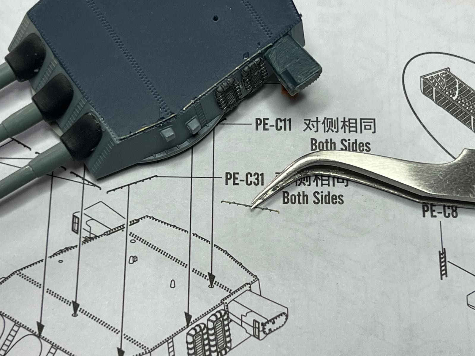
30 Kickplates
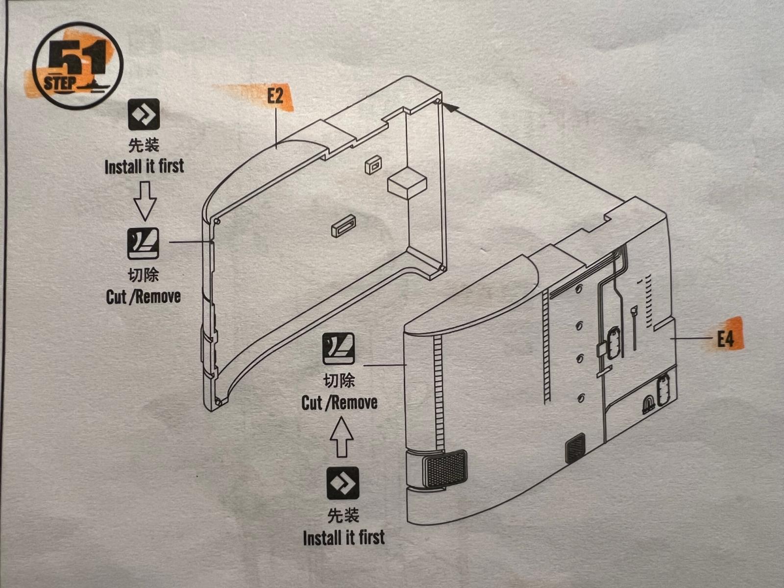
31 N27 Cutout
32 N27 subassembly install
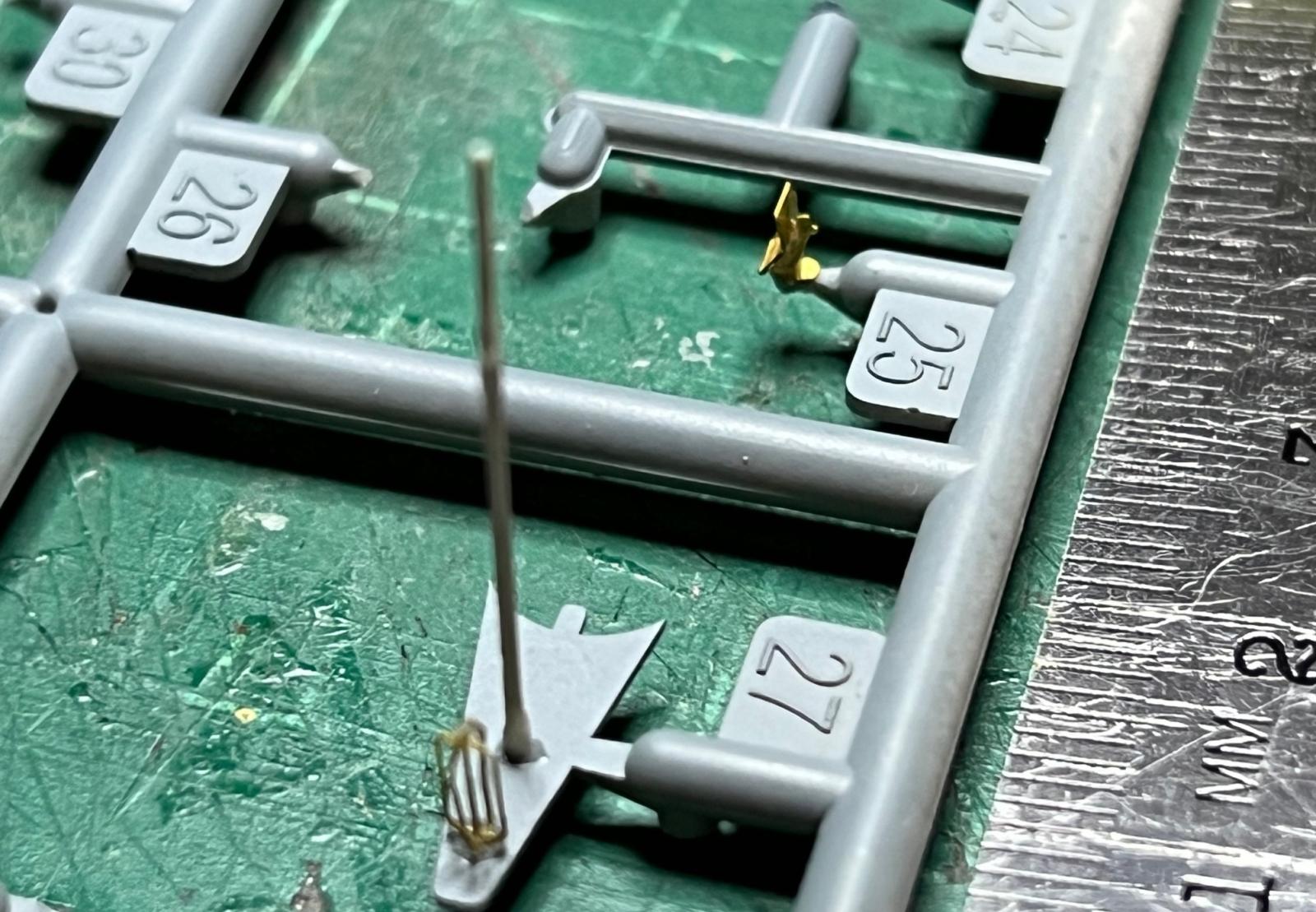
33 N39 and c-3 Assembled on Sprue

34 Platform in way of railing
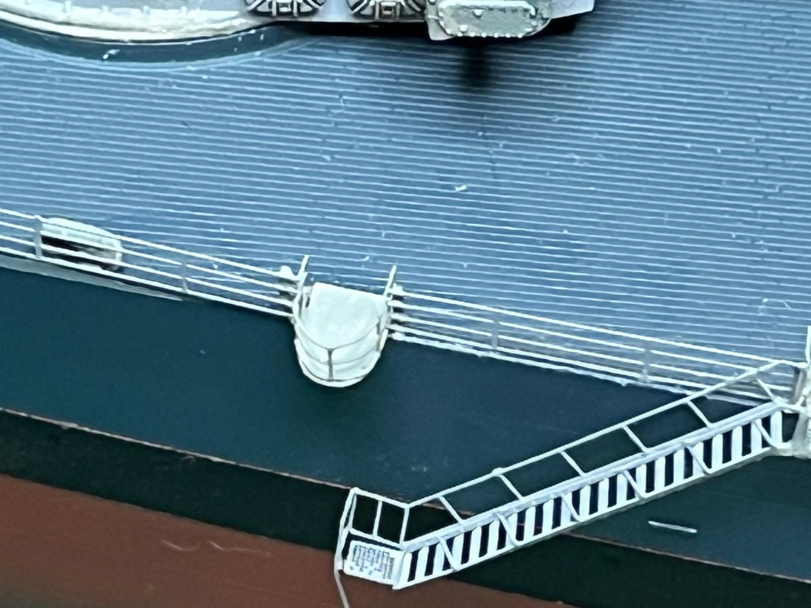
35 Railing cut to fit platform
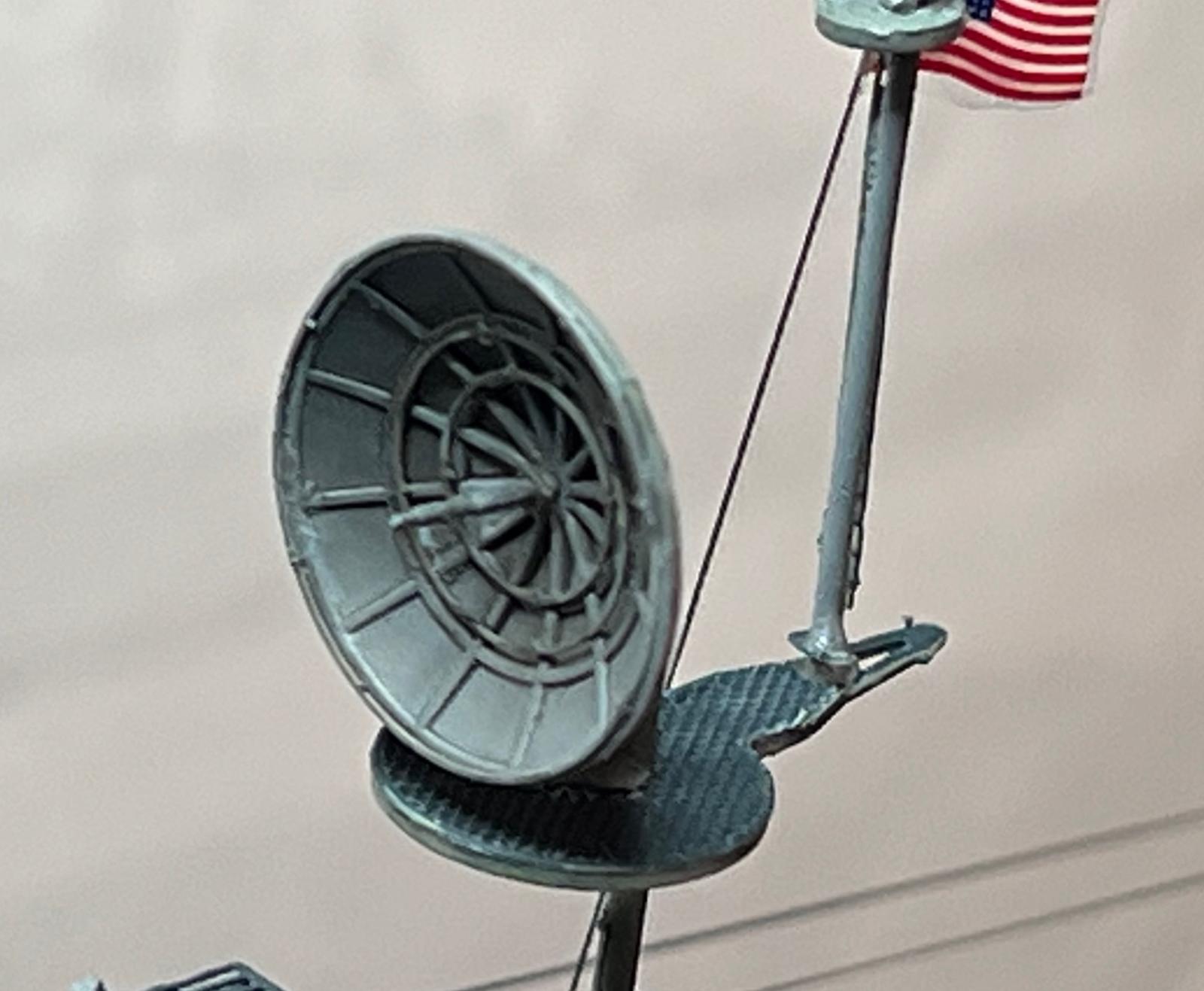
36 Main Radar Dish
37 Second Flag Rigging Line Extension
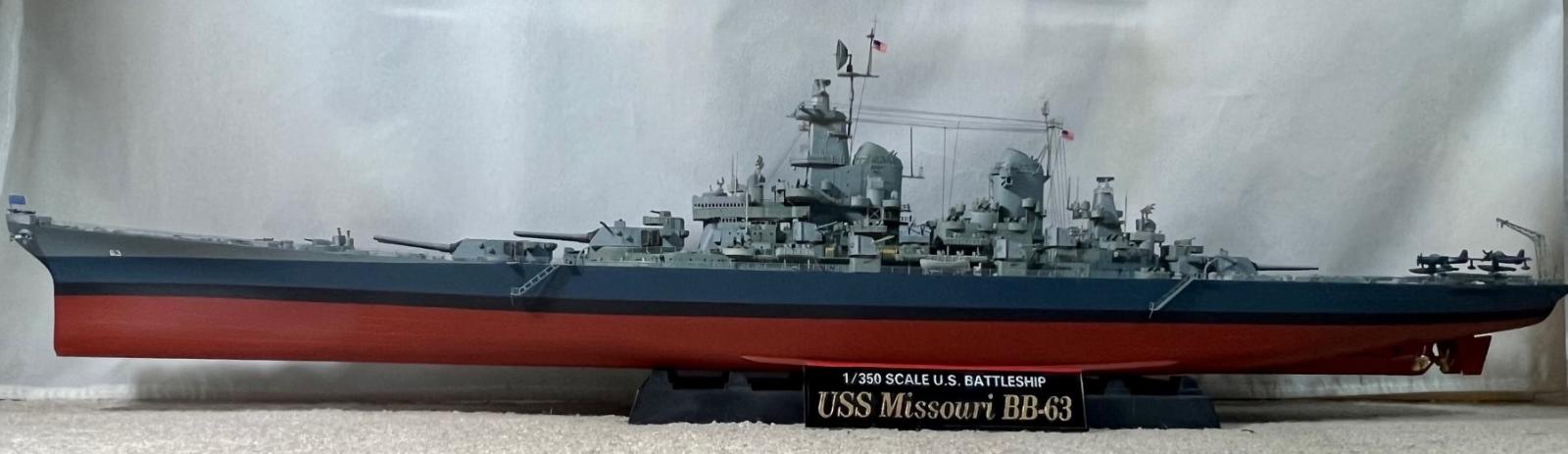
38 Port Side View
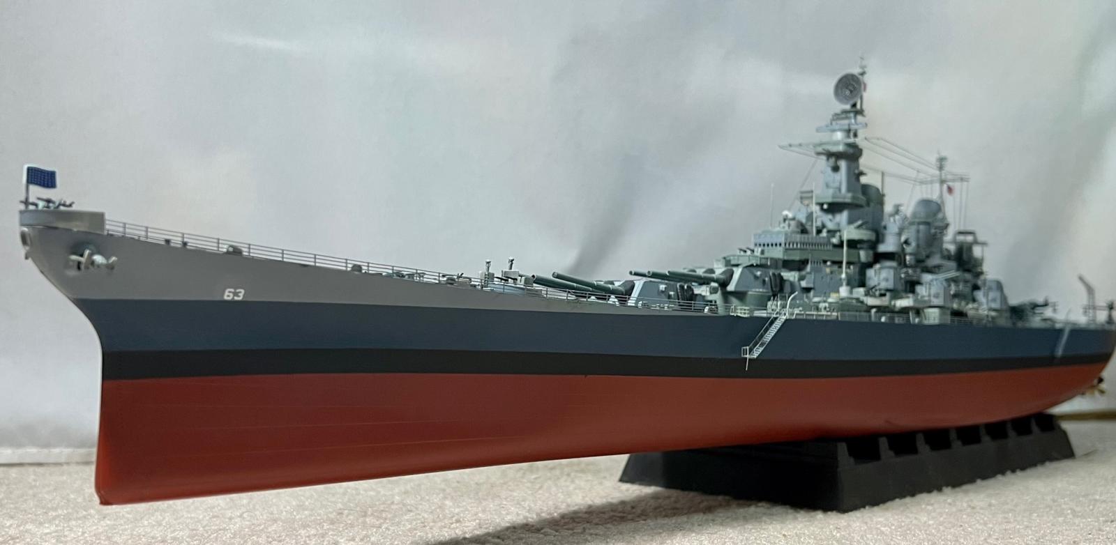
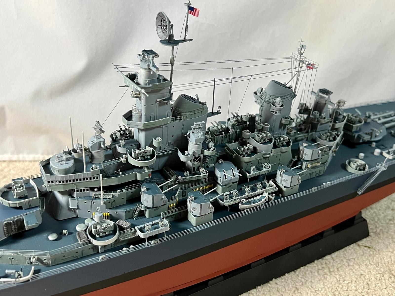
39 Port Bow Quarter
40 Port Stern Quarter
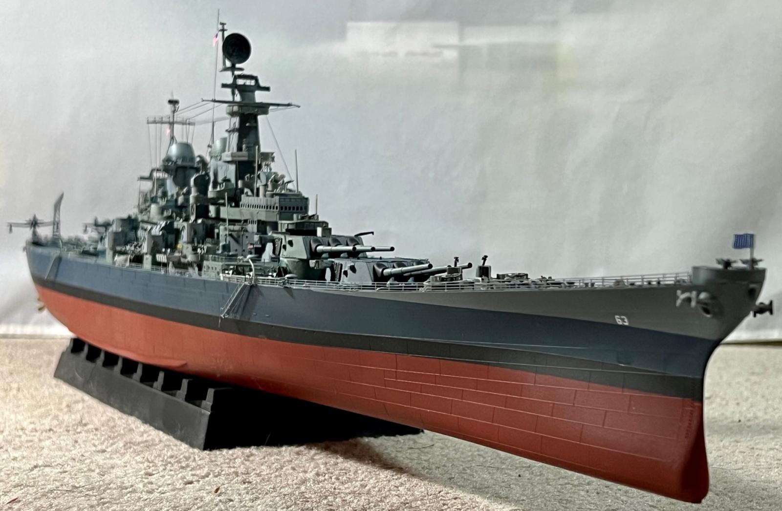
41 Starboard Bow Quarter
42 Port High Details
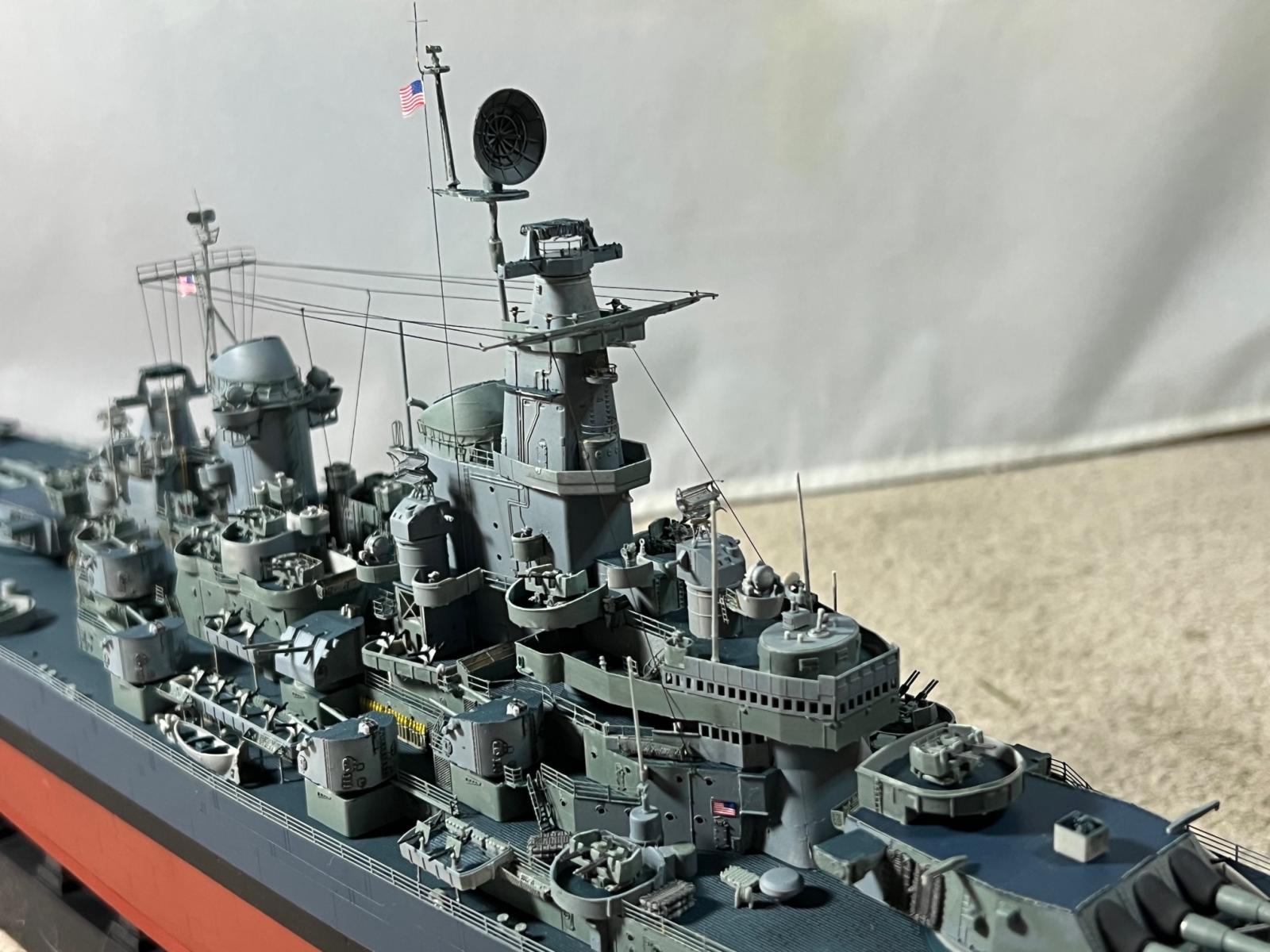
43 Port Side High Showing Rigging
44 Starboard Side High Rigging
45 Clean Bow showing Rail cut for Overhanging Platform
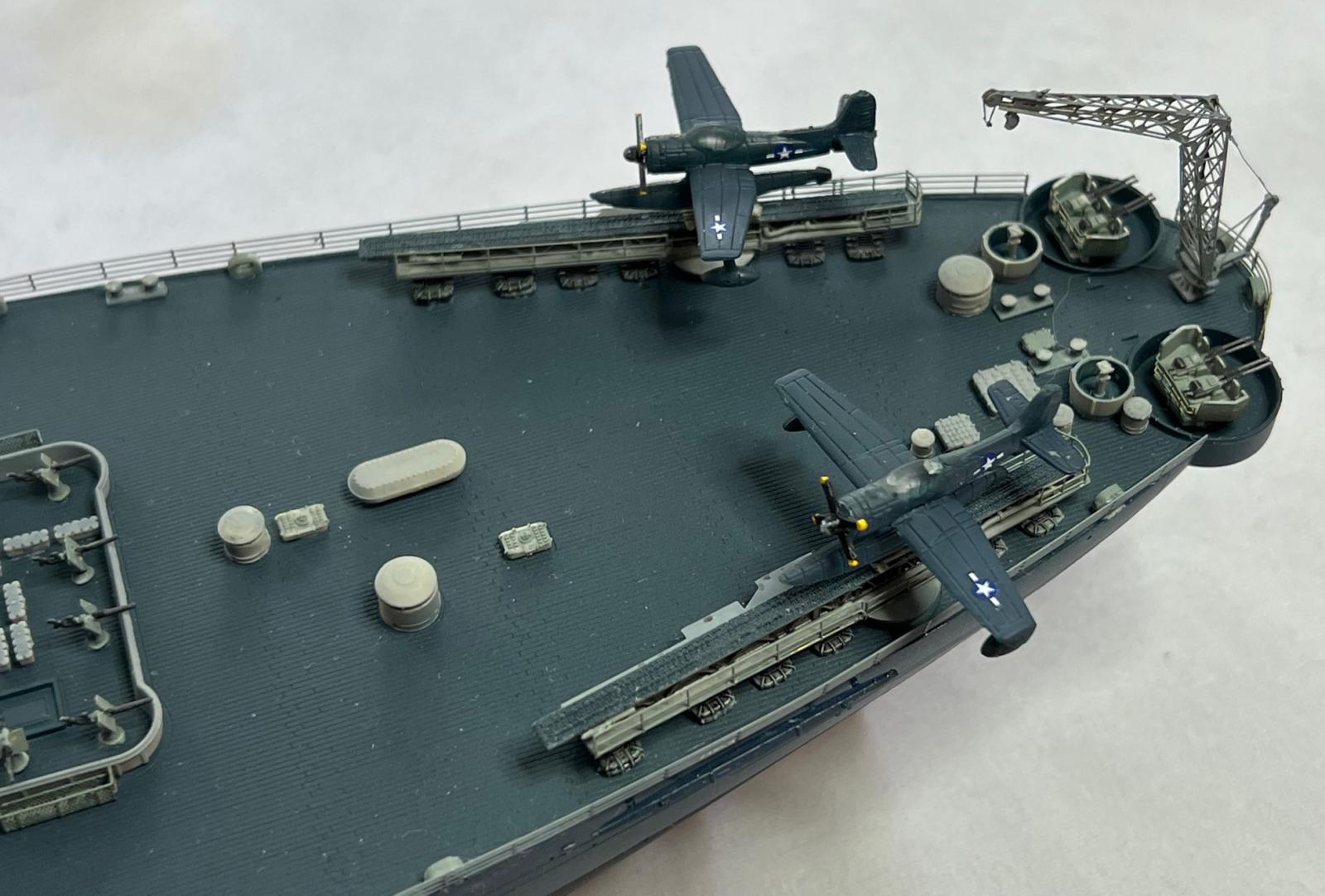
46 Stern with Seaplanes
Comments
Sterling missouri railing
What is used the the railing stanchions? I am rrestoring a sterling Missouri and I'm missing so m e railing stanchion
Add new comment
This site is protected by reCAPTCHA and the Google Privacy Policy and Terms of Service apply.
Similar Reviews