
Battleship USS Missouri BB-63, Part 2
Report 2: Midway through Construction
This second report covers the build from Steps 26 through 48 of 64. It is essentially the assembly of the upper decks prior to attachment of the stacks and their associated appurtenances.
Through this point in the build, most of the parts fit exceptionally well, to the extent that some can be press fit together. When you encounter one that doesn’t fit as well, like the life raft stacks, it makes you wonder if you are doing something incorrectly. The life rafts did not stack up evenly when placed one on top of another, so I used more glue than usual and clamped them in place after assuring they were parallel. Although good overall, one drawback of the tight fit is that a mere paint layer could interfere with making a tight joint or may require a pinhole to be reamed out before being able to attach a part.
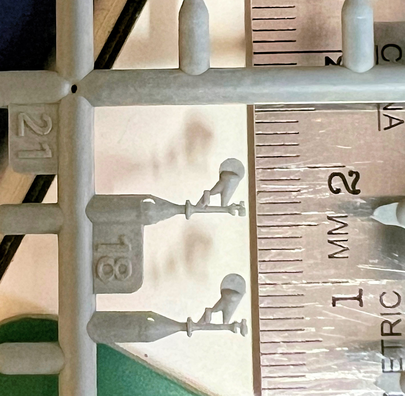
Most of the assembly and sub-assemblies went together fairly well through this stage of the build. My most concerning issue is the handling of the large number of extremely small parts. I don’t know if this is what an experienced ship builder normally deals with, but I found it frustrating. Parts M18 for example are not only very small to handle and clean of excess plastic but are attached in two places to the ejector pin, which makes it difficult to cut them off the sprue without being damaged or broken (See Photo 15). Also, some of the PE parts are so thin and delicate that it is almost impossible to cut them away from their sheets without distorting them (like the railings) or breaking them.
Some issues:
- One of the masts, Part L10, was broken on the sprue. All the masts are thin and require careful handling to avoid bending or breaking them when detaching from the sprues.
- I needed to refer to the Painting Guide to locate where to place the two Parts L63, as the instruction diagram (Step 40) doesn’t convey that they are centered in their deck space.
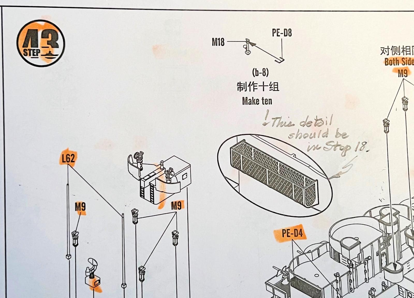
- A detail of the proper shape of the floatation device cages, Parts PE-D4 and -D5 is not shown until Step 43. Parts PE-D4 is introduced in Step 18 as a black blob in the instruction diagram, and I squared off the bottom of four of those by mistake. The detail of their shape should be in Step 18. (See Photo 16)
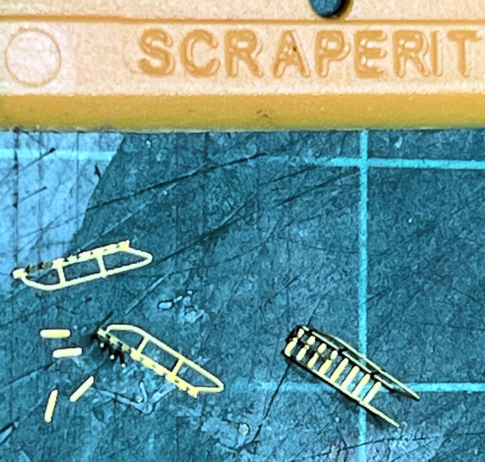
- The photoetch parts are very thin, so much so that a couple of them fell apart while bending. One example, are the stairs with railings, Part PE-C49, one of which went to pieces. (See Photo 17).
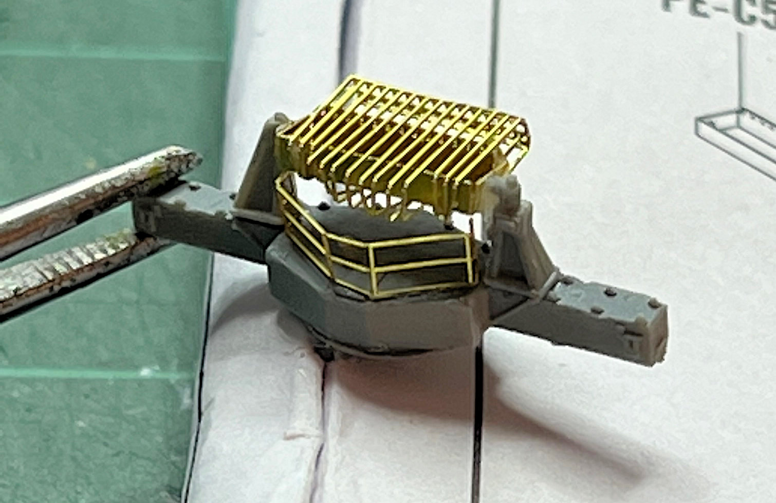
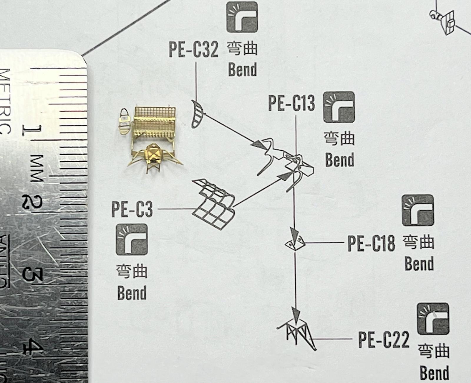
- Assembly of four five-part PE antennas (Step 44) was a challenge as the parts, in particular PE-C13 and -C22, are very thin and easily broken. Getting them properly shaped and trying to keep them that way, was not possible for me. Getting the oval-shaped side antenna cemented on was also difficult as there is little gluing surface for its attachment. I bent the bottom outside legs of Part C22 to provide gluing surface for attachment to Part P4. I settled for an acceptable but not perfect shaping of this sub-assembly. (See Photos 18 and 19).
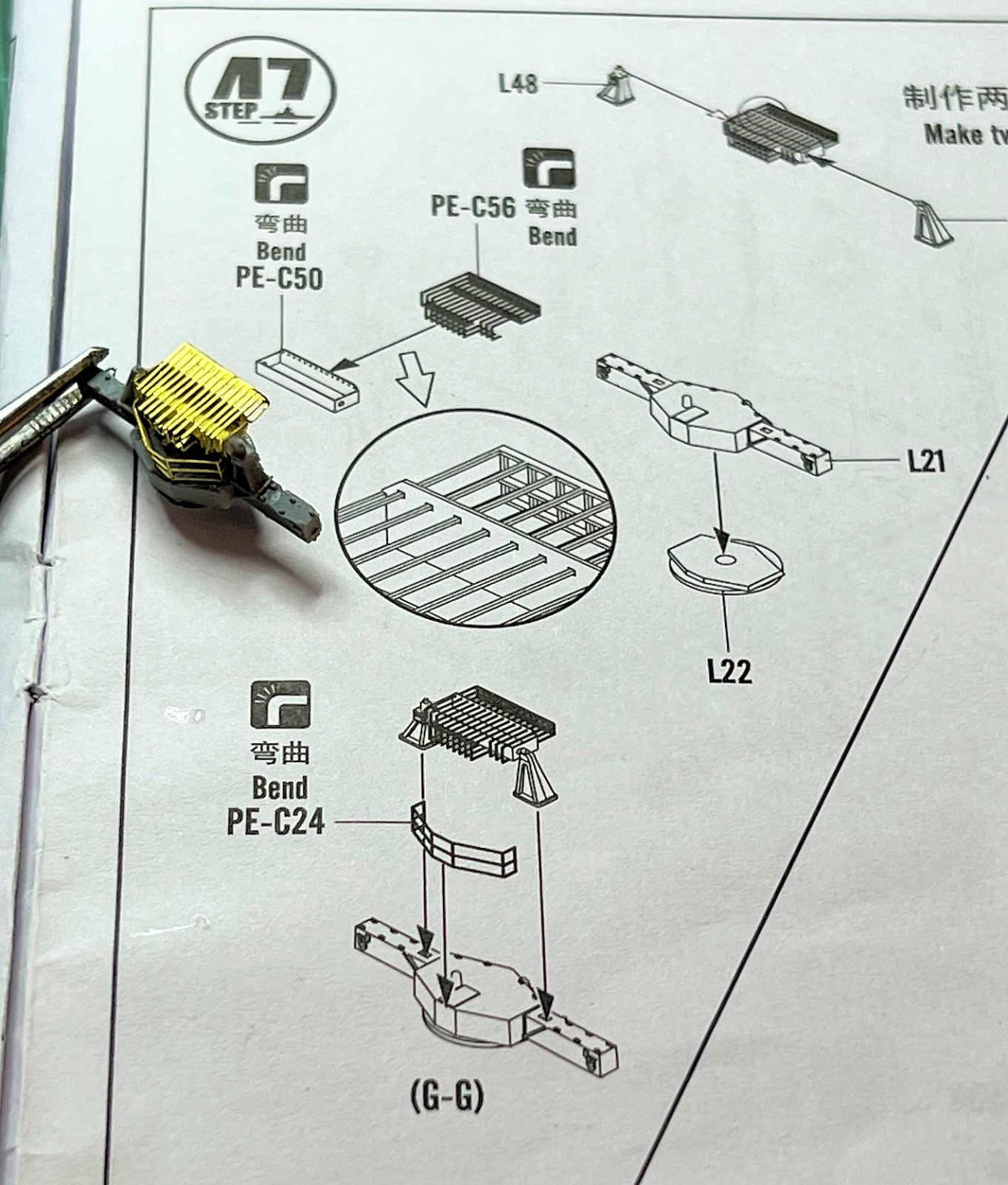
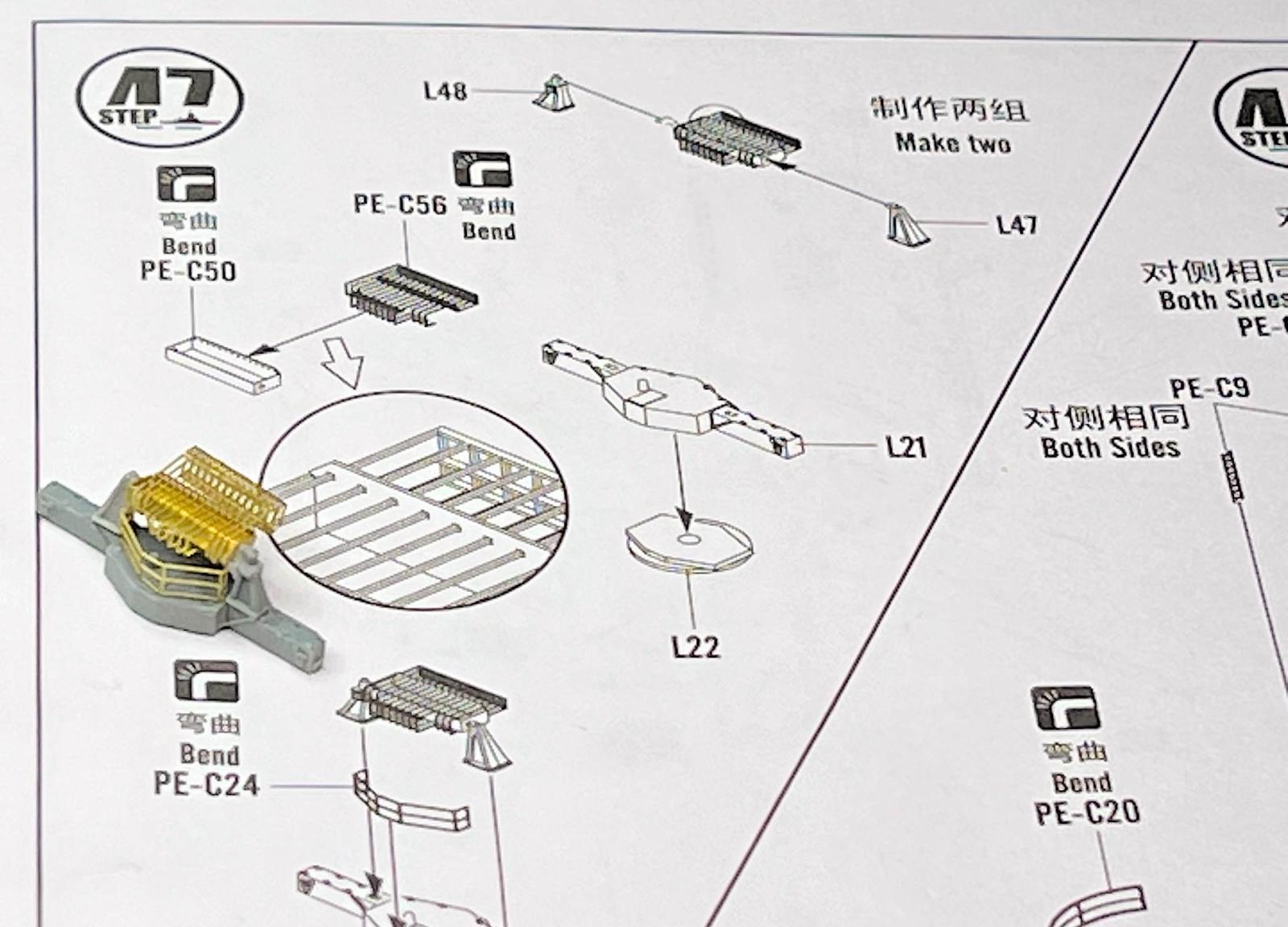
- Step 47 shows the diagram of what I believe is an oddly shaped radar where the tines of part PE-C56 need to be threaded through the tiny holes on the side of a pre-bent Part PE-C50. (See Photo 20). I found this to be an impossible task, as the tines are so thin that they are easily misaligned. After many valiant tries to get those tines threaded, I decided to run the tines over the top of Part PE-C50 and then bend them to shape. A couple of tines came off in the process. (See Photos 21 and 22).
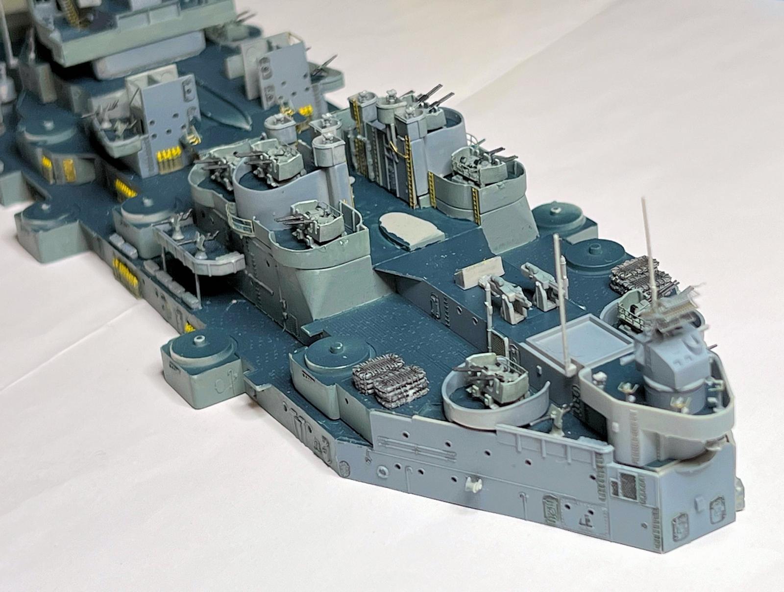
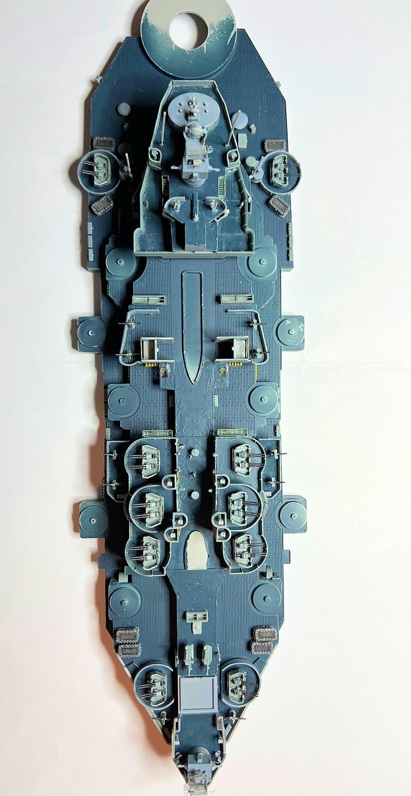
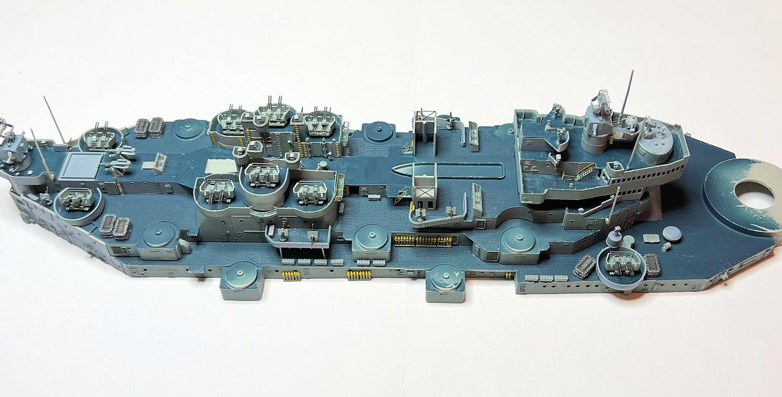
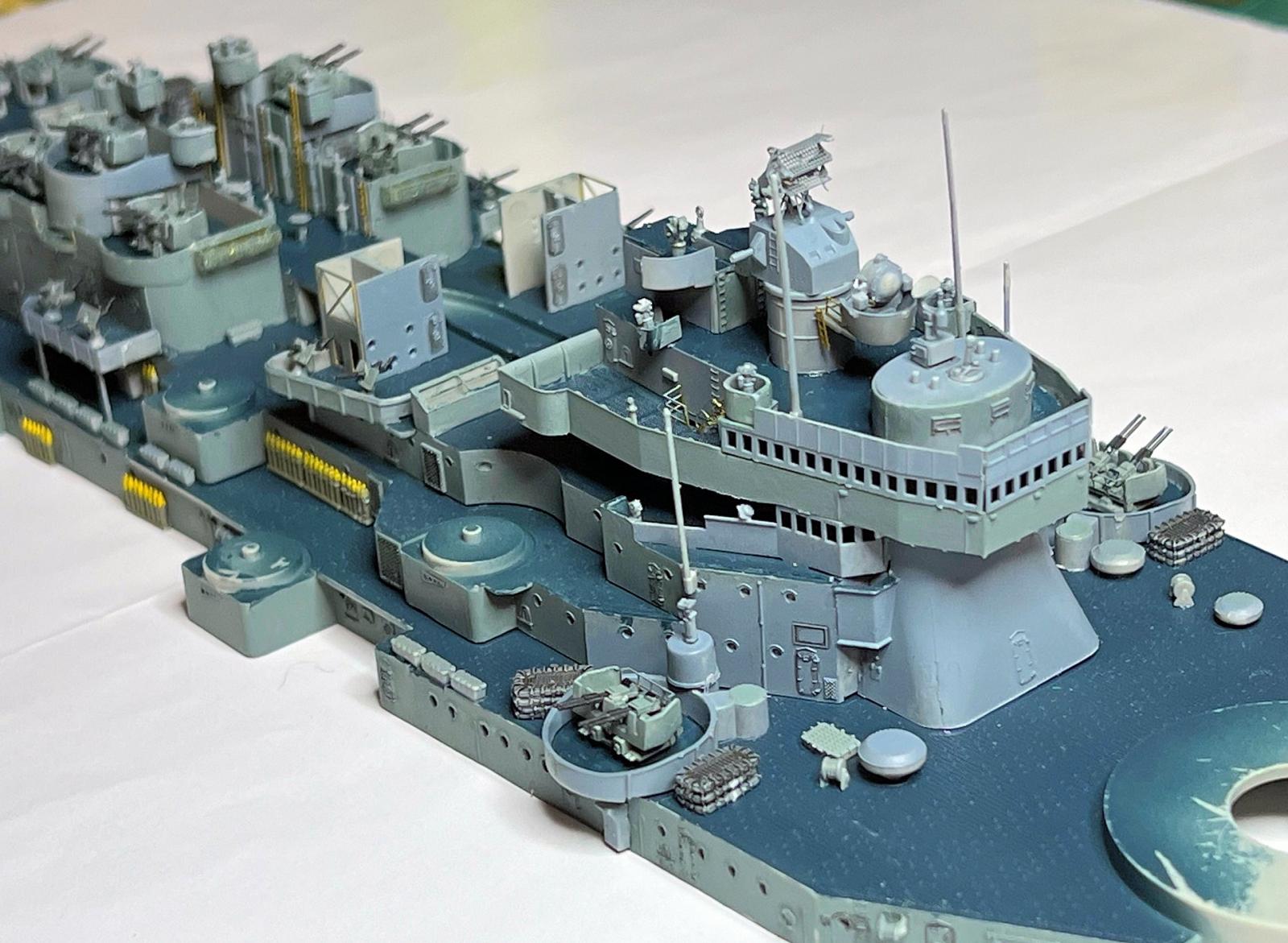
The assembled decks as of this point in the model’s construction looks impressive (See Photos 23 through 27). The issues of the small parts, the thin PE, and the lack of detail in the instructions makes for a challenging build.
As an inexperienced ship builder, I would love to see more detailed instructions with all the parts named, as was the case with most model instructions in the 1950s and 60s and done to a degree by some kit manufacturers in more recent years. With the latter, I could understand what each component was and look up photographs as references on each to see how they were actually constructed.
A third report will be issued after completion of the build. My thanks to Hobby Boss and MRC for the opportunity to build this kit.


Comments
Add new comment
This site is protected by reCAPTCHA and the Google Privacy Policy and Terms of Service apply.
Similar Reviews