
B26B-50 Invader Korean War
Kit
The Douglas A-26 Invader was an American twin-engine light bomber / ground attack aircraft. From 1948 -1966 it was re-designated as the B-26 and served in the Korean War from 1950-1953.
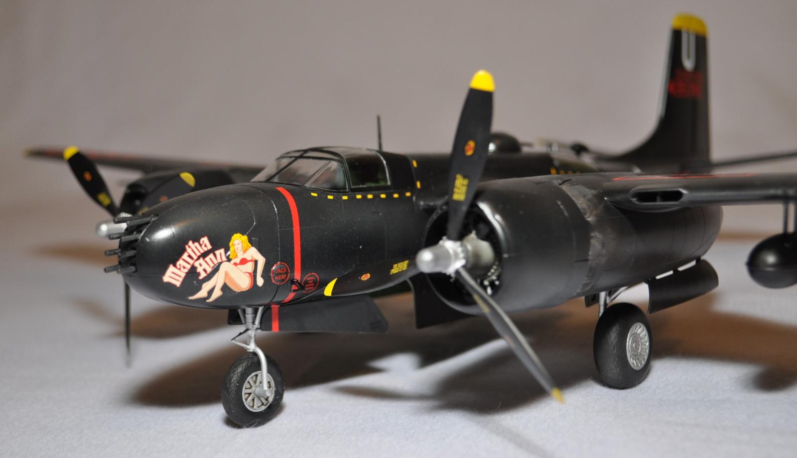
ICM Holding, a Ukrainian-based company known for outstanding quality, has produced a very fine plane with the release of the B26B-50. The finished kit will measure to approximately 12.5 inches length x 17.5 inches wingspan. Contained in the box is one sealed bag containing ten highly detailed gray styrene sprues and a separately bagged clear sprue. The kit contains a total of 245 parts which were all flash free and showed no injection marks or sink holes. Panel lines are finely recessed. A note of caution: in the review sample several small parts had become detached from the sprues. Be sure to carefully check the plastic wrapper before discarding. The 24-page assembly guide follows the typical aircraft building methodology. A very nice feature of ICM Assembly instructions is the full color painting and decal diagrams at the end. Assembly begins with the cockpit moving to the fuselage, wings/control surfaces, nacelles, wheels, engines, armament and lastly clear parts. Decals, also produced by ICM, are provided for three aircraft: B-26B-30-DL; B26_B-56-DL and B26B-61-DL. The aircraft in this review depicts B-26B-61 DL Martha Ann and uses the ICM B-26B/C Invader (Korean War) decal sheet item number D4802. This decal sheet is covered in a separate review.
Reviewer’s Comments
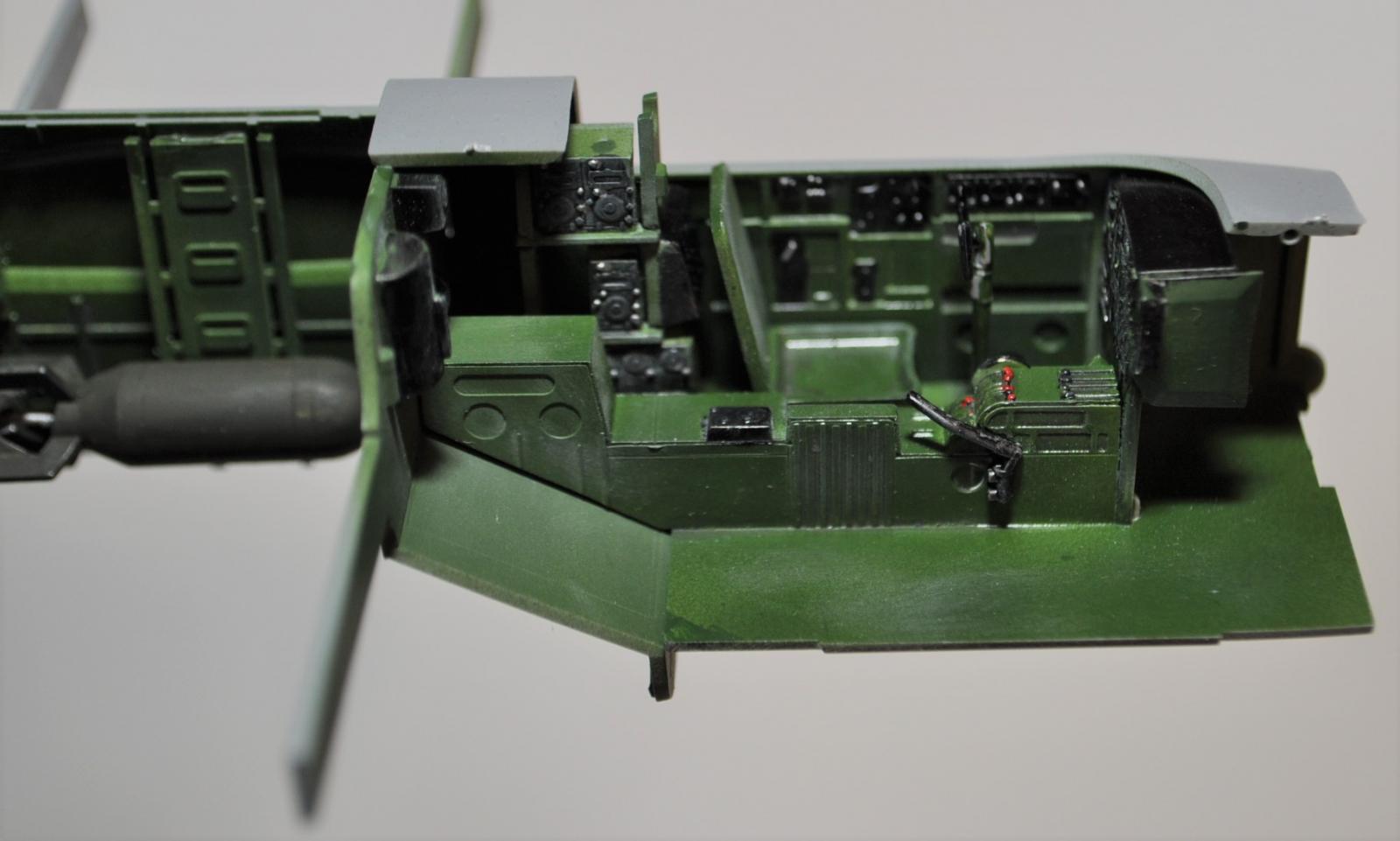
The cockpit is nicely detailed and the fit within the fuselage is excellent. An unexpected problem was, however, encountered in step 5 of the assembly. Decal number 5 (instrument dials) is to be applied to the instrument panel after it is painted black. Usually, instrument decals are one decal, however, after soaking the kit decal for a few seconds, the dials began to separately lift away from the paper and float in the water. Luckily, I was able to catch this right away. The builder will need to carefully transfer each dial decal to its location on the panel, but the end result is a nice-looking cockpit. Before the left and right fuselage halves are joined, the side cockpit panels, cockpit assembly, bulkheads, and bomb racks are attached. These all fit superbly. The builder needs to pay close attention to step 12, 15 and 16. In steps 12 & 16 a small clear piece (G6,G7) is fitted in the tail section of the left and right side. These are the tail windows. In step 15 you are instructed to drill a 0.08mm hole, which will later accommodate an antenna. These instructions are easy to miss.
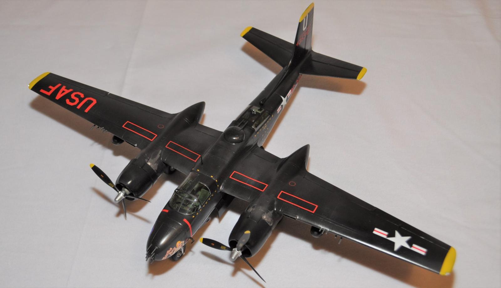
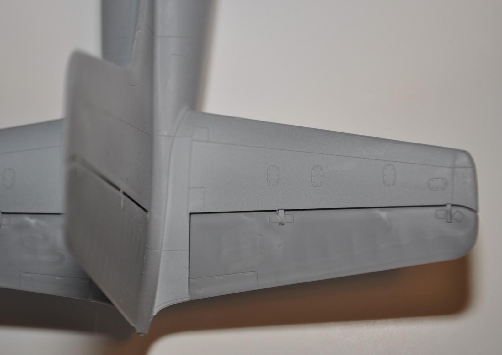
The fuselage halves join together superbly. In the review sample, the rudder and elevators fit so well that no adhesive was needed. Before attaching the wings, the builder is instructed in step 30 to drill a series of six holes in the bottom of the left- and right-wing halves to accommodate some but not all of the options of adding bombs, fuel tanks or gun pods to the undersurface (step 99). My recommendation would be to decide in advance which, if any, of the options you would like to use and then drill holes as needed to avoid having unneeded holes in your wings. The wing halves fit together very well and a light sanding takes care of any seams. The ailerons and flaps fit snugly and required no adhesive. Attaching the wings to the fuselage was easy and resulted in clean wing joints that required no filler.
The nose assembly consists of four pieces in addition to the guns. The instructions specify to insert a 40g weight (about 1.41 oz.) into the nose once it is completed. This is absolutely necessary, however, I had to add slightly more weight to keep the model from sitting on its tail. Although the nose fit the fuselage well, a slight amount of filler was needed in the seam.
Assembly continues with the engine nacelles. These are nicely detailed but a still a bit basic and the fit of all components is excellent. Attaching each to the wing surface is also easy and just as with the wings, the joints are well-engineered and virtually disappear. No filler was required on the review sample.
The top turret gun was disappointing. The edge of the turret dome is supposed to be glued to the edge of a collar piece (E48) sandwiching a section of fuselage in between. This is supposed to result in a turret that rotates freely. However, the surface area of these two parts is very small and numerous attempts to get these pieces to adhere to each other using a variety of cements failed. Ultimately, the top turret was mounted and became static. The guns also do not pivot up or down once the assembly is in place, although the instructions give the appearance that they should move. The bottom gun is static by design. The builder could improve the engineering of the top turret gun by adding an additional “washer” with more surface area for the turret to bind to or by creating a “t- or -bayonet mount ” as with tank turrets.
The landing gear and wheel assembly is straightforward. The wheel halves fit together well, but they did require some sanding and attention to the seams. The attachment points for the wheels are unusually small. Usually there is a length of axel that inserts all the way into the wheel hub. This kit has a small pencil-like tip to which the wheels attach. After adhering the wheels, the builder must allow plenty of time for the wheels to cure as to prevent movement and /or breakage. Inserting the landing gear into the nacelles was easy and are actually very stable once placed.
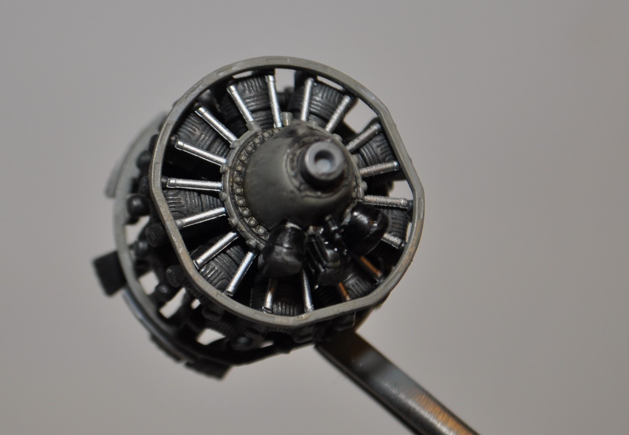
The engines are very nicely detailed. It is unfortunate that they are ultimately covered and that there is no option provided for having open engine access panels. Step 85 is confusing and the casual builder may be puzzled. Per the instructions, piece E34, called a “conductor”, is to be held in place without using adhesive while the exhaust pipes are placed into position. Since there is only one piece E34, you may find yourself wondering how to attach the engines. It turns out piece E34 is really a jig and its only purpose is to mimic the engine mount so that the exhaust pipes are in the correct position. Therefore, once your engine and exhaust pipes are fitted, piece E34 is not used and can be discarded.
Finishing out the assembly comes attaching the props, which fit very well and then adding the options of additional bombs, gun pods or fuel tanks. The clear parts fit extremely well. Builders who enjoy a lot of detail can take advantage of several after-market kits to enhance this kit, but out-of-the-box this kit was a joy to build.
Thank you very much to ICM for the honor of reviewing this very nice kit and thank you to IPMS for the opportunity.


Comments
Add new comment
This site is protected by reCAPTCHA and the Google Privacy Policy and Terms of Service apply.
Similar Reviews