
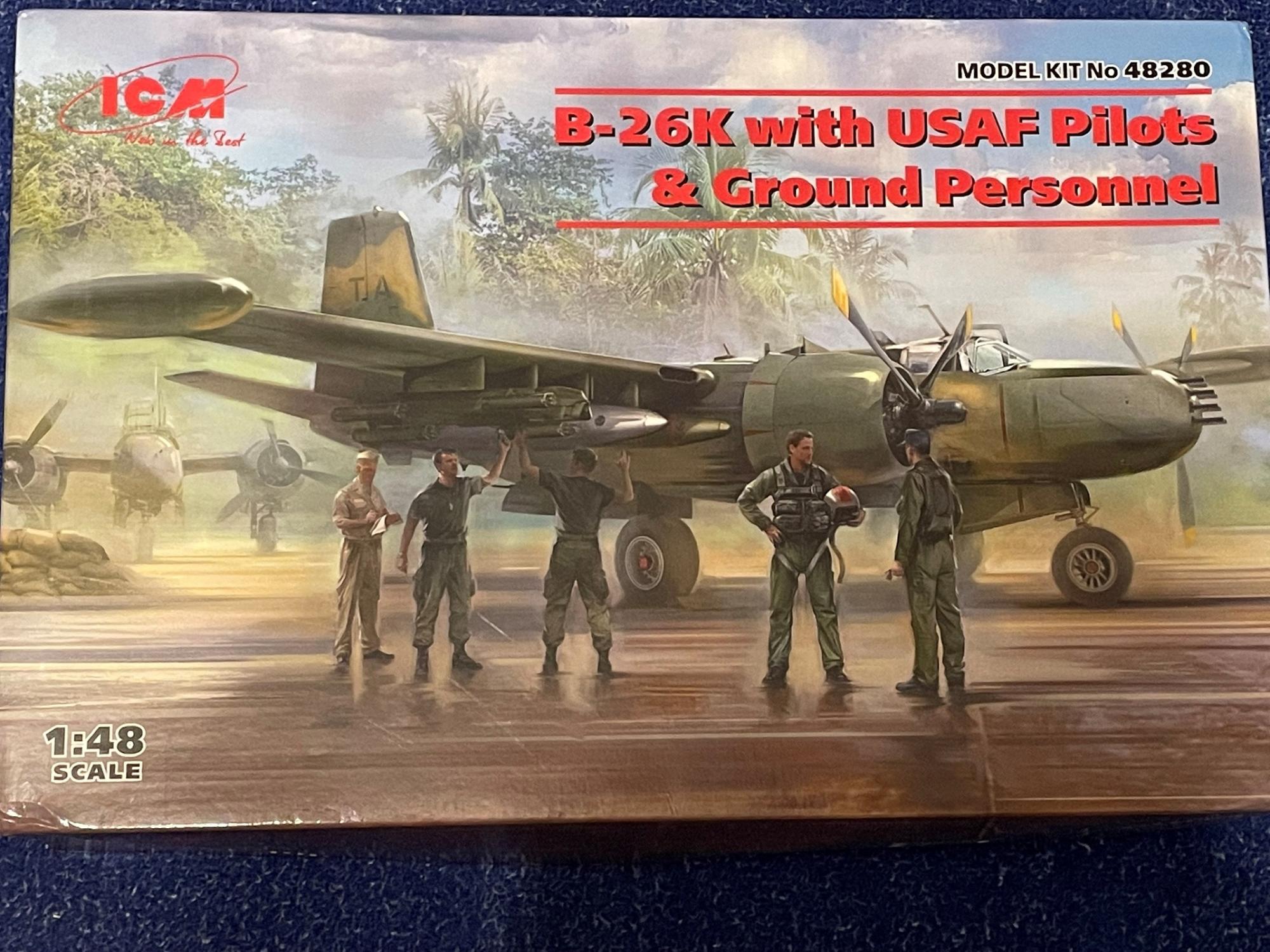
B-26K Counter Invader with USAF Pilots & Ground Personnel
ICM Is a Ukrainian company who has really made a name for themselves in the plastic model community. An informative history of the B-26K Counter Invader is included on the cover of the instruction manual and I took a picture of so it could be read there.
The model was contained within a very strong, lid opening box. The sprues were found inside several plastic bags which protected the parts. Three instruction manuals and two decal sheets were laying in the bottom of the box. In my edition a single sprue of US Pilots and Ground Personnel were included, as well as US Aviation Armament (four sprues), both in their own bag.
This was my first ICM aircraft model, and I was not disappointed. The parts showed lovely detail with appropriate recessed and raised panel line detailing. I found, however, that the plastic was very soft, even more so that the latest Airfix models I have built. The parts glued together nicely using Tamiya Extra Thin cement and could be sanded very easily. Care was taken not to over sand and damage the parts.
I was concerned that parts like the wings and fuselage were overly flexible and would present problems going together, but with bulkheads and other internal structures in place, the model was quite strong and fit very well in most cases. I found that nearly all locating holes were not deep enough for the length of the pins, so I drilled the holes deeper to achieve a flush fit of each part.
Mold seam lines were minimal and there was almost no flash on the parts.
An intriguing find in the box was that all the parts were still there to build an earlier B-26A or B model. A complete set of earlier wings, shorter chord rudder, engine cowls, propellers, canopies and turrets were included – A lot of unused plastic, but a nice addition!!!
Construction started with building four bombs, followed quickly by fuselage bulkheads, the rear observer’s cabin and his equipment and the cockpit. ICM recommended that the cockpit be painted “lime” green which I took as zinc chromate. Pictures online showed the B-26K had a black painted cockpit, so I used Tamiya tire black. I was unclear about the observer’s cabin, so I painted that black too. In hindsight, I think this should have been bronze green. The bomb bay was also painted bronze green.
The cockpit looked accurate against pictures, if a little simplified; however, the two control column yolks were the older style. I would have liked photo etched seat belts included for each seat as they were quite visible (I used two Eduard photo etched color seatbelt sets meant for the “B’ model). A decal for the instrument panel was included and conformed to the raised and recessed detail extremely well. I think a few more instrument and control panel decals could have been included for the large center console and left side panels. Nevertheless, what is there is quite adequate, and I know the aftermarket have since released their photo etch and three D printed sets.
I assembled the wings next and there were very few pins to locate the top and bottom halves together. I used Tamiya Extra Thin Liquid Cement and aligned the parts carefully. The very flexible and soft wing parts became sturdy after the glue had set. The flaps and ailerons built up nicely and the trailing edges were some of the sharpest I had ever seen, Wow!!
The tailplanes and elevators were then built and fit great.
The B-26K included tip tanks on the ends of the wings. They fit together fine and flawlessly to the wing ends, but the prominent fuel filler caps were missing.
Both engine nacelles were built and contained quite nice detail in the wheel wells, although the roof of the wells was bare. I glued stringers made from Evergreen plastic strips which added some detail. Interestingly the gear doors which included part of the internal structure needed to be assembled at that time.
I followed with assembling both radial engines. They were beautifully detailed and little construction kits all by themselves. Unfortunately, unless a cowling is left off, little will be seen through the tight-fitting cowls.
With the very soft plastic I broke the propellor shafts very easily. I drilled a hole through the front of each engine and inserted a brass tube. Brass rod was then glued into the rear of the propellor hub that fit snuggly into the tube. An easy solution to one of the few, weak parts of the kit.
In step 88, part E34 named a “conduktor” was shown fitting to the rear of the engine, followed by adding nine separate exhaust pipe stacks. Initially, I thought there needed to be two of these parts, but I could only find one! I searched everywhere for several hours thinking that I had lost one, only to discover that there was only one and E34’s sole purpose in life was simply to aid in aligning and seating the exhaust stacks so they sat flush against the nacelle!!! It took a radical act of studying the instructions and parts diagrams to discovering the true reason for the part and see that there was only one part. I did question what “Conduktor” meant right at the start and might suggest to ICM different wording like “exhaust alignment tool” or something like that to help those of us who are a little IQ challenged 😊!
With the exhaust stack/Conduktor drama behind me, I turned my attention to the wheels and landing gear. When built each main and the nose gear leg were stronger that they first appeared. Each was painted aluminum with chrome oleo’s. The tires were in two halves each, as were the separate rims. This made painting each a breeze! The instruction manual illustration showed each tire having a radial tread pattern, but the plastic kit tires had not tread pattern at all. I attempted to scribe in the tread, failed and had to fill them in with super glue. The main wheel rims and antilock brakes were accurate for this aircraft. I ended up purchasing Res-Kit wheels that included the tread pattern and used the kit main wheel hubs which fit almost perfectly and the complete Res-Kit nose wheel and tire.
The fuselage halves were glued together with no problems, although I used super glue as a filler on several joints that I had trouble mating (my problem, not the kit’s). There was a separate panel that attached to the rear belly which replaced a similar part that would hold the belly turret. I ended up with a fairly large gap and used Evergreen sheet to fill the gap. I sanded it flush and re-scribed the panel line.
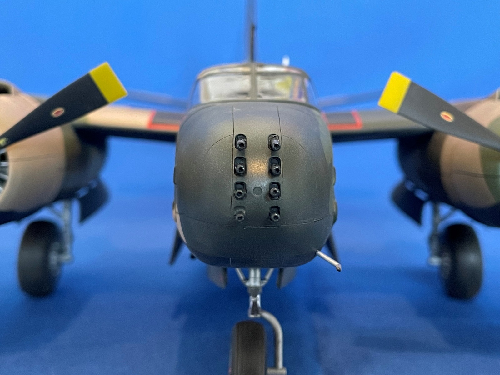
The nose consisted of four parts, each joining on a panel line. I was able to align each part pretty well, although I ended up with a gap on the upper right side. I glued a small section of Evergreen plastic sheet against the raised edge and sanded it flush. I also cut squares of the same Evergreen sheet and super glued them along the internal joints of the nose as additional strength inside the nose, especially as 40 grams of weight was to sit in there. While assembling the nose, I found it important to concentrate on the alignment, so it fitted flush against the forward fuselage. For me, the nose assembly was the most labor-intensive work in the entire model. However, I was very happy with the end result!
Two sets of four guns each were positioned in the nose. I drilled out barrel ends. Forty grams of weight was recommended and I loaded steel scrap metal weights into the nose and forward fuselage. The nose was then superglued carefully to the fuselage.
The wings were glued to the fuselage. I have rarely experienced such a perfect wing to fuselage fit in other model aircraft that I have built! They fit flush at the wing roots and aligned themselves with the use of spars that set the dihedral flawlessly. The tailplanes mounted in their slots precisely too. They fit so nicely I just had to position them and run Tamiya liquid cement along the seam to secure them in place. DONE!!! Great job ICM!!
When building the wing pylons, it is important to keep them organized as they are dedicated to either the left or right wing. The correct pylons fit their slots perfectly.
The canopy and other “glass” parts were beautifully clear, but I still treated them to a dip in Future Floor Wax. Both cockpit and observer cabin canopies fit very nicely, as did a small window in the rear cabin door. A small hole needed to be drilled into the roof of the cockpit canopy to accept an antennae mast. Measurements are given to position the hole.
Canopy and window masking templates were provided in the back of the instruction manual. I used them by photo copying them to a separate sheet. I then taped the template sheets I needed inside a clear plastic sleeve and laid blue 3M tape over the outside of the sleeve. Shining a light underneath the sleeve (attached to a glass table top) revealed the masking template through the tape. Using a new X-acto blade I carefully cut out the masks and applied them to the canopies. For the most part they fit perfectly.
The engines were attached to the front of the nacelles and mount into a tear drop shaped slot that aligns the engines perfectly. The cowls slide over the engines followed by attaching the cowl flaps at the rear. Unfortunately, the cowl flaps could only be attached in the closed position.
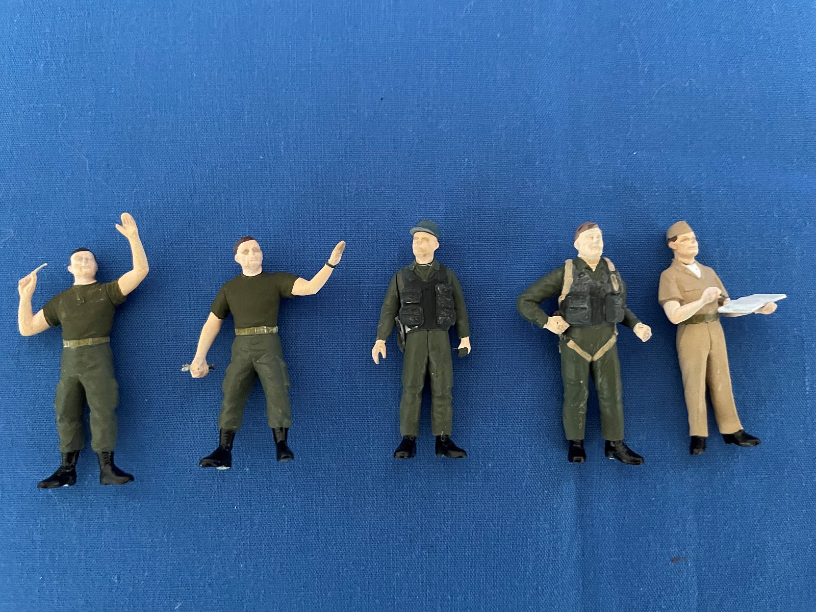
With the aircraft mostly built, I turned my attention to the single sprue that contained the two pilots and three ground crew figures. Each built up very nicely from separate legs, arms, heads, and equipment packs. The detail on each figure was outstanding. I left off heads and arms for easier painting. I followed the separate instruction sheet to assemble and paint each man. I am certainly not a figure painter, but I enjoyed building these crew members. The attached pictures show the faces to be much more pale than they actually are.
A nice selection of US Aviation weapons were included. Four sprues contained everything that could be carried on the B-26K and more. I built what I intended to use and kept the rest for any future build that could use them. Decals were provided for each weapon and performed well.
Both the ICM crew figures and the armament are also available for purchase separately.
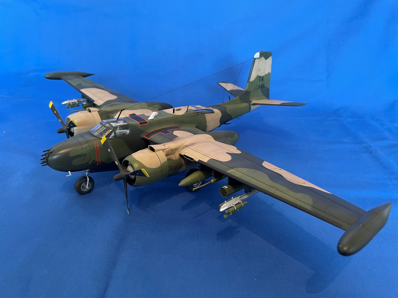
I prepared the aircraft for painting and spent some time studying the glossy, color painting diagrams. I chose to paint the third version – B-26K 64-17645, 56th Special Operations Wing, 609th Special Operations Squadron, Nakhon Phanom, Thailand, 1969. This aircraft had an interesting history: This aircraft originated as an A-26C Invader and was rebuilt by On Mark as a B-26K. It was used by the CIA in the Congo from 1964 to December 1966 with the tail code RF-645 and later FR-645. In August 1967 it arrived in South-East Asia and was turned over to the South Vietnamese Air Force from the USAF on November 10th, 1969. Unfortunately, the aircraft was blown up in 1975 at Nha Trang to prevent it from falling into the hands of the North Vietnamese.
I started by painting the entire aircraft black, followed by tan and the two green colors. Masking the soft edges between each color was done with poster putty/BluTak, rolled into long thin “snakes”.
A gloss coat was painted, and I tackled the decals. They were thin but performed beautifully. A further gloss coat followed to seal the decals, and when dry, I ran a black wash over the sides and upper surfaces and a medium grey wash over the black underneath. A final flat coat was sprayed over the entire aircraft. These washes show how petite the panel lines are on this model.
With the painting done, I attached the three landing gear legs. They all fit very nicely and were just strong enough to support the weight. The wheels were then added to each leg and she was finally able to stand on her “feet”. Aftermarket metal landing gear legs may be a good investment, as I could see that over time the legs may start sagging a bit resulting in the wheels splaying out. Another solution would be to drill a hole through the length of the leg and insert a metal rod to add strength to the soft plastic.
The armament was glued to the wing pylons. The attachment points were minimal, so I added a short length of wire to each weapon that ran through a hole drilled into the pylons. This added ample strength.
The canopy masks were removed and proved that the masking templates worked very well. Antennas were glued in their slots and fishing line was used to replicate aerials and a whip antenna. After taking the pictures and just before submitting this review, I noticed there should be another arial that runs from an antenna on the fuselage roof to the fin, just below the black de-icing boot. That will be added in due course.
This will certainly not be the last ICM model I ever build! ICM has done a fabulous job on the B-26 Invader range. The fact that all the parts were still there to build any of their earlier models was outstanding. And, in the case of this boxing, the inclusion of the crew figures and complete weapons was a very nice touch to add a bit more interest.
I would recommend this kit to modelers with some experience, simply because of the softer plastic, however it is certainly not out of reach for any modeler to achieve a great looking model of this impressive aircraft.
Thank you very much to ICM and the IPMS USA for entrusting me with building and reviewing this model. I thoroughly enjoyed every minute of it!


Comments
Add new comment
This site is protected by reCAPTCHA and the Google Privacy Policy and Terms of Service apply.
Similar Reviews