
AR-2 (43105) Special Fire Hose Truck
Summary
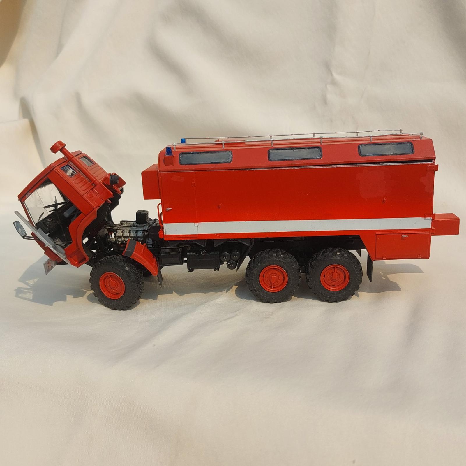
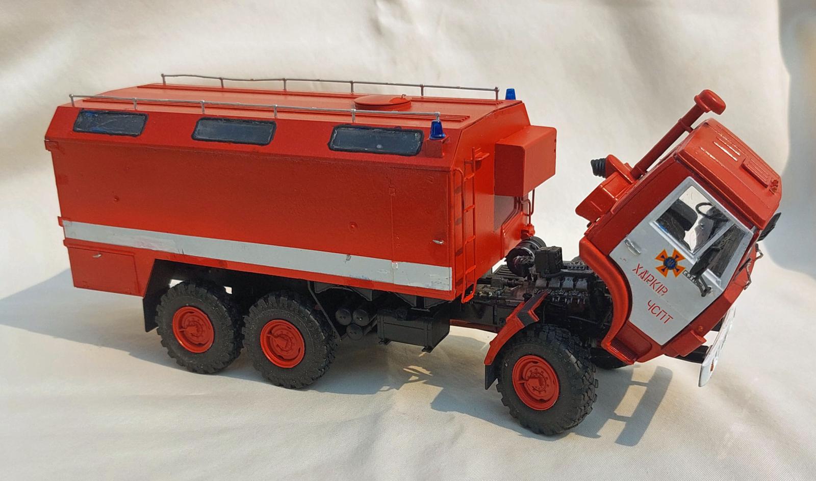
The kit is an extremely well detailed version of the civilian AR-2 (43105) 6x6 in service as a special fire hose truck. The model has a complete chassis with a full engine, a well detailed cab, and a fire hose box with outstanding exterior detail. The fire hose box itself is empty. So if one wanted to display the doors open an interior would need to be fabricated.
Background
The following is excerpted from the instruction sheet.
The special fire hose truck AR-2 (43105) is designed for mechanized laying of fire hose lines from the fire site to a water source. The vehicle is based on the off-road KAMAZ-43105 6x6 chassis. A specially prepared chassis is fitted with an all-metal body with side and rear doors. Inside, the body is divided into two compartments. The front one houses fire-fighting equipment, while the rear one holds fire hoses. The body is also fitted with adjustable racks that form sections of different sizes. The vehicle operates with a three man crew, a driver and two operators. The first operator is responsible for controlling the fire hose assembly mechanism, while the second operator monitors the laying out of the hoses. The vehicle carries enough hoses for a line of up to 2.5‑kilometers in length. This operator also controls the placement of the hoses in the box after use.
What’s in the Box
- 1 large bag with 6 sprues of light gray plastic.
- 1 medium-size bag with 1 sprue of clear parts.
- 2 small bags of clear parts.
- I medium-size bag with seven rubber tires.
- 1 small sheet of decals, with markings for three vehicles
- An 8-inch by 11.5-inch instruction booklet with five view images for painting and decal placement for the three vehicles that can be modeled.
- The Instructions
The instructions consist of a 32-page glossy 8-inch by 11.5-inch instruction booklet. The front cover provides a brief description/history of the vehicle, including technical data. ICM paint colors and descriptions of the various pictorial symbol/notes are also on this page. Pages 2 thru 5 are parts maps for each of the six sprues. These drawings also note unused parts (suggesting the possibility of other versions of the KAMAZ-43105 vehicle to come). Pages 6 thru 29 are the assembly instructions. The images are sharp and show the assembly as an exploded ¾ view. The final three pages (030 thru 32) have three exterior five view painting guides for the three vehicle decal options provided.
Things to consider before starting
There are four areas where options are available. The front axle can be modeled solidly forward or turned. The cab doors can be modeled opened or closed. The cab itself can be modeled tilted forward or down. And, finally the widows of the hose box can be modeled as clear or painted over (depending on which vehicle is modeled). Decisions on what you want can be made at the correct step in the instructions. But once made cannot be undone.
Another item to watch is mold seams. The instruction drawings are actually very detailed. I noticed that after assembly many of those parts where shown in other steps actually show a separation line along the mold or joint lines. I made the assumption that these separation lines are real and attributed to poorer manufacturing methods. So, before going off and removing all mold and seam lines, check future steps to see if they show up as “real” separation lines. Some things, such as radiator hoses and exhaust pipes I did clean up. But most other items I left the seams alone.
Construction
I start all my builds by scrubbing the sprues with an old toothbrush in warm water and dish soap (Dawn) to remove any residual mold release residue.
Chassis, Engine, and Wheels
Like most vehicle models assembly starts with the main chassis. This is made up of two side rails and four cross‑members. There is also a winch assembly and rear cross-brace that also act as cross members. As with any model with separate side rails keeping the frame true and square is critical to a well fitting kit.
Steps 1 through 3 cover construction of the winch assembly and rear cross-brace. Step 4 adds these items as well as separate cross-members to the right-hand main rail. The leaf springs for the front wheels are molded as part of the side rails, saving the frustration of fitting and alignment. Steps 5 and 6 cover assembly of small parts that are added later. In step 6 check part A33 to make sure all the holes are open. I had to drill out the hole for the engine drive shaft. Step 7 adds the left hand side rail to complete the main chassis frame. Steps 8 thru 10 add parts to the frame such as a rear towing hook, front cross-brace, and the assemblies from Steps 5 and 6. Note that parts A12 and A57 are shown attaching to the wrong side rails. Because of the shape of the attachment points this is pretty obvious during construction.
Steps 11 thru 13 start assembly of the rear suspension. Steps 14 and 15 assemble the front bumper and attach it to the frame. I deviated from the instructions and left the front bumper off until I had painted the completed chassis.
Steps 11 thru 26 cover assembly of the engine. This is a well detailed mini-model, but I was unable to find any reference photos to add any additional detail, such as electrical wires. I deviated slightly from the instructions here as well, preferring to assemble all the steel parts and paint them before attaching the other parts. I also pre-painted those parts either flat black or rubber black for hoses. Step 27 mounts the engine to the frame. Be aware that the engine mounts have triangular notches that fit over the triangular part of the frame mounts, giving a good solid gluing surface. Steps 28 and 29 assembly and mount the radiator. Steps 30 thru 33 assemble and mounts the exhaust pipe to the frame. Once again I deviated from the instructions leaving off the engine and exhaust until after the chassis was painted. I did attach the radiator though. Leaving off the engine and exhaust until after the chassis is completed and painted required a little bit of careful threading under/over/around parts, but was not difficult.
Steps 34 thru 44 assemble the rear suspension components and attach it to the chassis. Step 45 builds the rear differential and drive-shaft. Note if you are painting the completed chassis then do not attach this as called out in step 50, but wait until the chassis is painted and the exhaust is installed. Leaving this part off makes installation of the exhaust much easier.
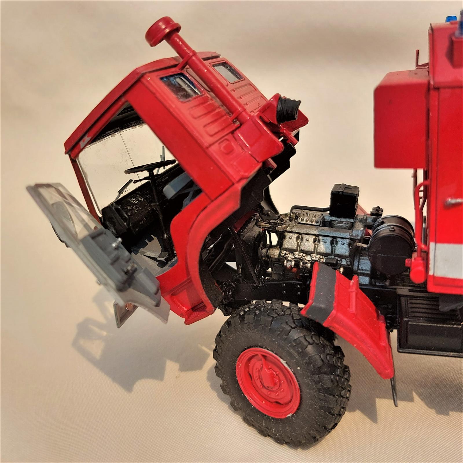
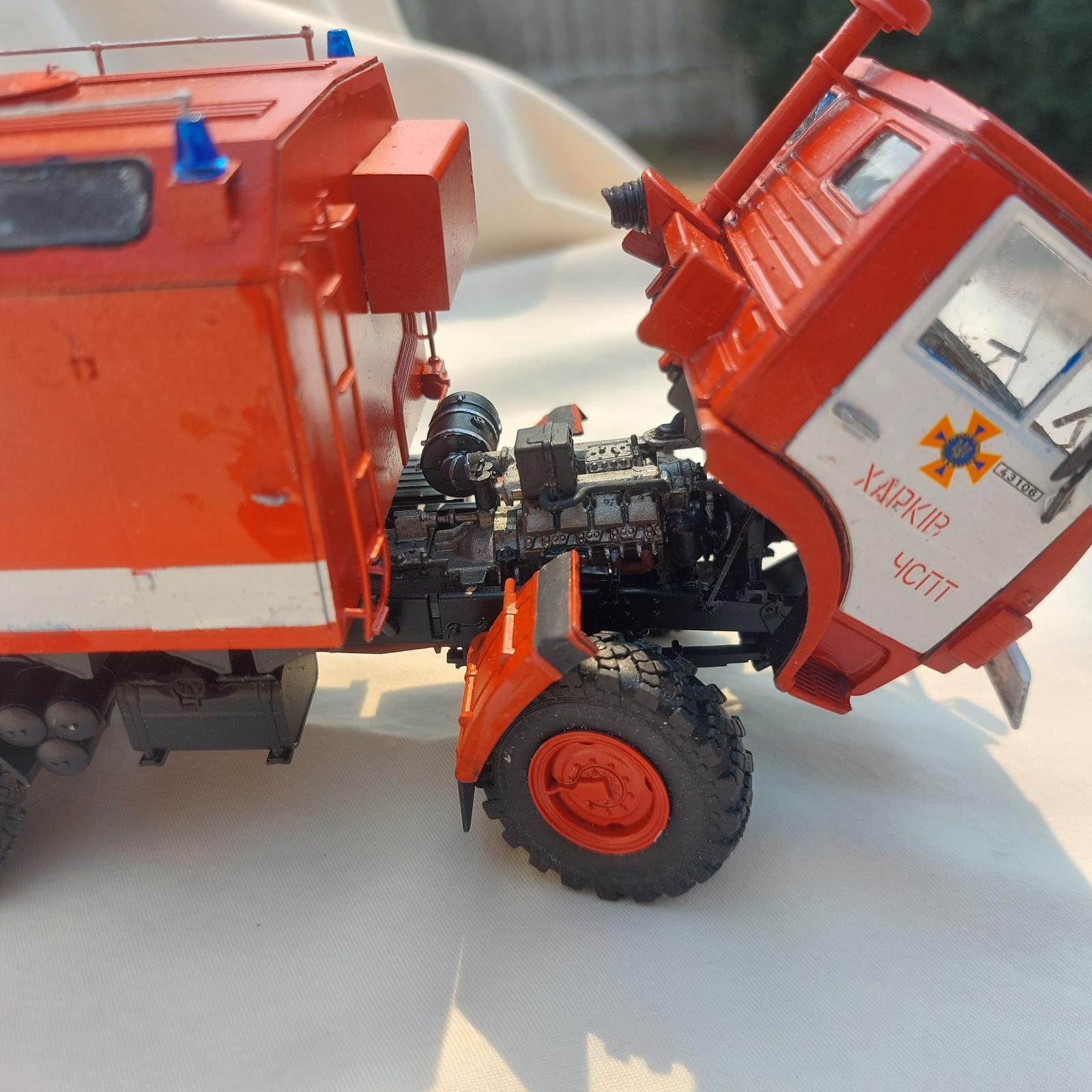
The first optional step comes at step 46. The options are split into left-side/right-side configuration. Steps 46 thru 52 left-side build a front axle with the wheels solidly held straight. Steps 46 thru 52 right-side builds a front axle that can be modeled turned to one side or the other. And, with a minor bit of surgery, can be made to function, as I will explain later. Whether modeling the turned wheels glued or functioning the groove in the completed axle (parts F22 and F23) must be filed deeper for the control arms to fit properly. Special care should be used in steps 46 and 47 as parts F20 and F21, while looking the same, are very different.
Steps 53 thru 64 complete the chassis with the addition of fuel tank supports, fuel tanks, battery box, and compressed air cylinders. Note that in step 55, if the wheels are assemble turned then part F13 need to be modified, (either shortened or lengthened). I built the mudguards in Steps 61 and 63, pre-painted them dark red on top and black underneath and left them off until after the chassis was painted. In step 58 pay attention to the clamps on the straps around the compressed air cylinders. The clamps should point down and to the front of the chassis. This requires some dry fitting to make sure they are installed correctly.
To make painting easier I built the majority of the chassis (as well as the box attachment frame (Steps 70 thru 72). There are no paint callouts for any of the chassis or suspension parts, other than the exhaust pipes. Referring to the painting guides it is clear the chassis is black, even though it is not called out. I went a step further and, assuming that fire trucks tend to be well maintained, paint the chassis semi-gloss black. After that had dried I attached the engine and exhaust pipe. Another deviation I made here was noting the attachment of the mudguards to the chassis. It is by way of two small pins. Looking at them they just cried out to be installed so that they could be broken off multiple times. Therefore, I left them off until near the completion of the build. This turned out to be a good thing. Another caveat I will put forward here is that the compressed air cylinders should also be left off until near the end. They also have a small attachment point and I broke off both during construction and only got them reattached using CA glue.
Steps 65 thru 68 assemble the wheels, while step 69 attaches the completed wheels to the chassis. Although the rear wheels (Steps 65 and 66) and front wheels (Steps 67 and 68) use the same parts, it is critically important to pay attention to the tread pattern. The reason the hubs are shown attaching from opposite sides is so that when the wheels are attached the tread patterns on both side are the same. If this were not done the tires on one-side would end up backward to the tires on the other side. So, pay attention. It is also very important to note that in Step 69 the chassis/frame is bottom up. As with the tires, if the wheels are put on the chassis when it is right side up the tread pattern will be backwards. As an aside, the kit comes with seven tires even though only six are used. My guess is that the seventh tire is for a spare in an upcoming kit.
Fire Hose Box
Steps 70 through 101 assemble the hose box, while step 102 attaches the completed box to the chassis. I deviated a bit here for painting. To ensure things lined up when attaching the box to the chassis I assemble the attaching frame (steps 70 thru 72) and temporarily attached that using white glue to the chassis and painted the whole thing.
Because of the different paint colors I bounced around a bit to facilitate easier painting. I removed the attaching frame and temporarily glued it to the box floor (step 73). I then painted this gloss black. I then removed the frame to make masking the black underbody later easier. I then assembled the under floor storage boxes (steps 74, 85, and 86), the ends (Steps 75, 78, and 79), and the sides (steps 80 and 81) attaching them all together as shown in Step 82. To avoid gaps in the under floor storage boxes I found the installing the inner walls (step 74) and the front and sides to the floor (step 82) first, followed by the front panel (Step 86) and the top (step 85), then cementing the box rear provided a much better “seal” around the under floor boxes. After assembling the fire hose box I sprayed the interior of the open box and underside of the top (part K1) with the top hatch (part L35) attached with sky gray. When that had dried I installed the windows into the top (Step 83). At this time I also temporarily attached (again with white glue) the top to the box. I then installed all exterior parts from steps 85 through 101 on the assembled box that would be painted either red or white. I attached part L45 to the top as shown in step 97, but left the clear blue light off until after painting. I also left off the front mud guards (part L18), the wheel chokes (step 88 and their hold-downs (step 89), most of the small silver handles (part L41) and the top railings (part L2). Most of these parts were pre-painted and attached after painting of the main box.
Once all but the small handles and roof rails are attached and painted the completed fire hose box is glued to the chassis.
Cab
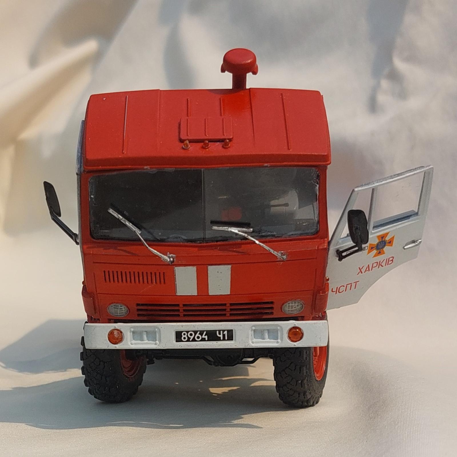
Steps 103 thru 141 covers assemble of the cab. In step 106 the option being called out highlights the one serious error in the instructions. Steps 143 and 144 although labeled “Assembly Variant 1” and “Assembly Variant 2” the drawings are identical. Step 143 is in error and should show the cab installed down on the frame. If you have decided to model the cab closed (down on the frame) then install part F18 to the cab floor now and do not use part F52 in step 143. Alternatively, if you want to model the cab tilted forward, I would recommend carefully removing the plastic from where part F18 would attach. Although really a minor nit, I think doing this results in a more realistic look at step 144 where the gear shift goes through the floor into the cab instead of having the gear shift on the engine and a solid cab floor above it.
Once more to facilitate painting I deviated a bit from the assembly instructions. I followed steps 103 through 114, skipping step 113 to leave the seat separate. I also did step 116, 117, and 137 thru 138, but left the glass out of the windows (step 115). In step 138 be careful that the upper bracket of the air intake is below the step at the top of the cab wall or else the roof will not sit properly. I also attached part B29 to the cab roof (part B30). Although only the seats have a paint call-out the entire cab interior (rear wall, roof, floor) (except for the cab front) is neutral gray. After assembly I sprayed the interior and seats neutral gray. When that had dried I installed the seats onto the cab floor (step 113).
I assemble the dashboard (without the decal) (Step 121) and used white glue to attach it to the cab front (step 122). I also completed the steering wheel (step 124). I then painted the interior of the cab front, dashboard, and steering wheel semi-gloss black. After the paint had dried, and with some judicious dry fitting I found I could install the dash board with the cab front attached to the rest of the cab. I pre-painted the cab underside (part B22) before attaching it as shown in Step 118. I added parts B4 and B5 in step 119 to the cab front before attaching the cab front to the cab (step 123). Once glue on this assembly was dry using blue painters tape I masked the rear window and windshield openings from the inside. I also masked the door openings with blue painters tape. Using white glue I temporarily attached the cab roof (as shown in step 127). I then painted the cab deep red. After the paint dried completely ( I left it overnight) I removed the roof and window and door masks. I then installed the rear window glass (step 115), windshield (step 120), dashboard (step 122), and steering wheel (Step 125) into the cab interior. I also completed steps 119 and 126 by adding the clear parts.
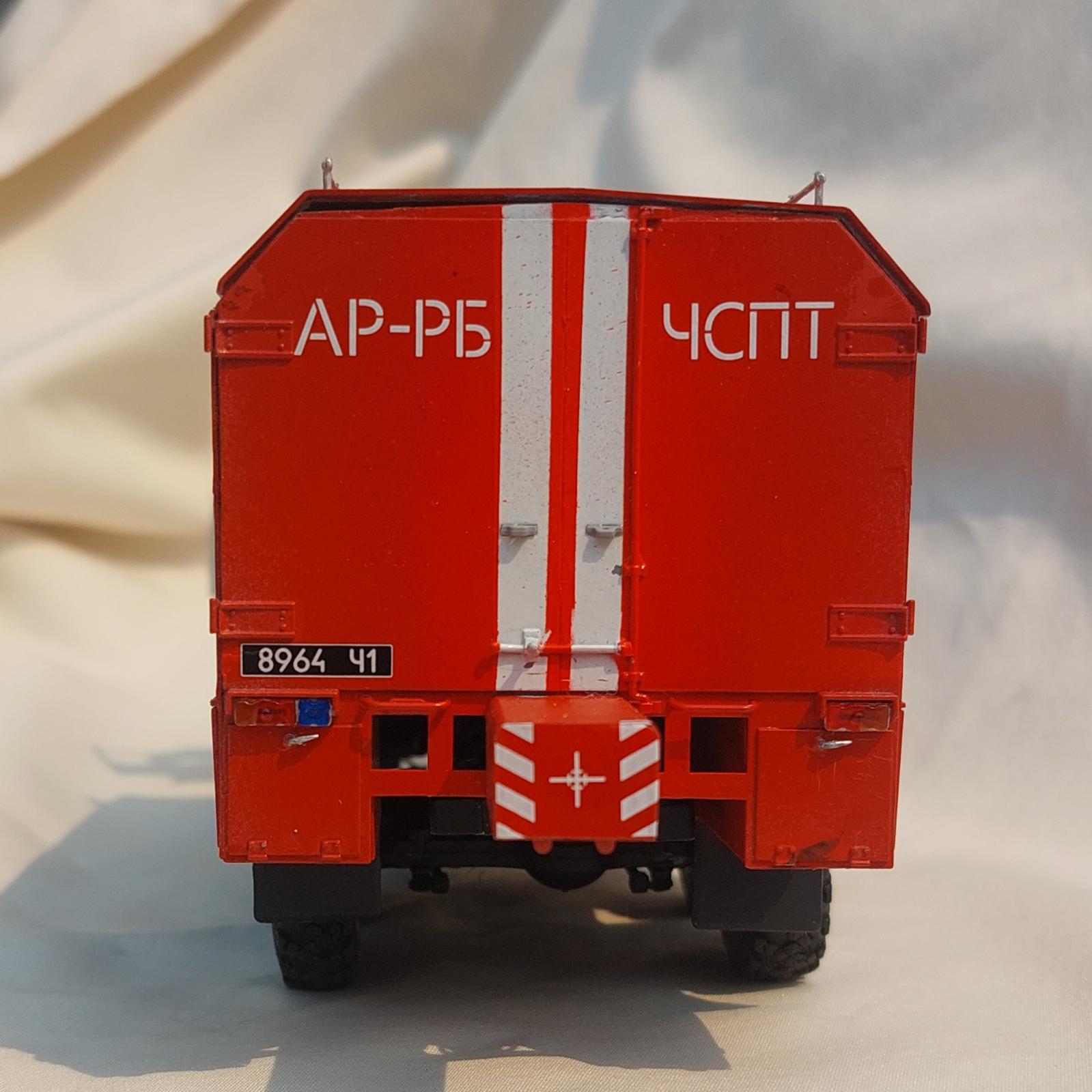
To complete the doors, I first painted the interiors of parts B20 and B21 sky gray, and pr-painted parts B2 and B3 neutral gray. After the interior paint had dried I painted the exterior of both doors white. I painted the door while they were still attached to the sprue so I had something other than the door itself to hold onto. After the white paint had dried I applied a coat of gloss varnish to the doors. When this dried I applied the decals for the version I wanted to model (Vehicle 3, Kharkiv, 2015). After a day I applied a second gloss cost to seal the decals. I then completed the doors as shown in steps 128, 129, and 133, 134. I left the mirrors off until final completion. I modeled one of each type of door. I modeled the driver’s side door is open while the passenger’s side door is closed. Note that to model the door closed the hinges must be removed from the door.
Final Assembly
Step 142 is the first step in the final option available. The cab can be modeled down on the frame or tilted forward (to show off the engine). It is clear in the instructions that parts F3 and F4 are for the cab tilted and that F46 and F47 are for the cab closed. As noted earlier step 143 is incorrect. For Step 143, Part F52 SHOULD NOT be installed and the cab should sit flat on the frame. Step 144 IS correct and part F52 IS to be installed.
With the cab mounted I then went back and installed all the small (aka highly breakable and/or losable) parts. This included the handles (parts L41) on the fire hose box and the top railing (part L2), and the mirrors (steps 130, 131, and 135, light lenses (steps 119, and 126), and searchlight and windshield wipers (step 140 and 141) on the cab.
And with that I had a completed model of a very interesting fire truck.
How to Make the Front Wheel Steerable
With some careful surgery and replacement the front wheels using the right-side option for steps 46 thru 52 can be made to be not just turned, but steerable. To start with replace the outer pin on part F49 (Step 5) with a short length of similar sized stiff wire. Next replace the tie arm pins on parts F20 and F21 with a similar sized wire. Also replace the control arm pin on part F20 with stiff wire. Carefully drill out the ends of part F17 (tie rod) where it goes over the ball joint pins (F20 and F21). Place the ball joints on the balls at the ends of the axle. Put the tie rod over the ball joint pins and make sure the wheels are square to one another. Very carefully place a small drop of thick CA glue on the top of the ball joint pins to “lock” the tie rod down. Be real careful to not cement the tie rod to the ball joint pins or all is for naught.
The next step is to modify the control linkage (part F13). First, drill out the connecting bolt between the short and long arms of the control linkage. Using a very thin razor saw (or similar tool) separate the long arm from the shorter control arm. Saw between the arms so that there is a “knob” on both parts when done. Drill out the connection at the top of the short arm. Use care to preserve the bolt detail. Glue a short length of stiff wire into the lower hole of the short arm of part F13. Slide the long arm over the wire pin and secure with a small drop of thick CA on top of the wire, being careful not to glue the long arm. Next, insert the wire pin on part F49 into the top of the short arm of part F13 until it is flush with the top of the molded bolt. No glue is need here as the motion is only forward and back, and not side to side. Attach the long arm of part F13 to the control pin on part F20, and you’re done.
Painting and Finish
The chassis assembly and suspension, engine and engine parts, fire hose box mounting frame and floor, and the entire F sprue where first primed with Krylon Fusion All-In-One Matte Black paint + primer. All other assemblies were primed with Krylon Fusion All-In-One Matte Glacier Gray paint + primer.
After priming the completed chassis was sprayed with Tamiya Semi-Gloss Black (X-18) as was the box attaching frame and box under floor (part K4). The assembled engine was brush painted Model Master Steel (1420), while the black parts were brush painted Model Master Acryl Flat Black 4768. The assemble exhaust was primed with the Krylon flat black and brush painted with Model Master Enamel Rust 1785. Door handles, window handles, and windshield wipers were brush painted Model Master Enamel Chrome Silver Trim.
The windows on the Fire hose box were masked with painters tape and Micro Mask. The black under floor was masked off with frog tape. The white stripe was roughly masked and spray painted with ICMs White (1001) from their Fire Trucks Acrylic Paint Set (see separate product review). After allowing that dry for 24-huors the white stripes were masked and the box was painted ICM Deep Red (1007) also from their Fire Trucks set. To get as bright a white and red as possible it is advisable to use a light colored primer. I used a light gray, but believe white would have been a better choice. After the red was dry to the touch the white stripe and window masks were removed. The rubber seal around the box windows was painted ICM Rubber Black (1039), again from the ICM Fire Trucks paint set, as were the wheel chocks and engine radiator hoses. Finally the top rails were primed with Krylon Glacier Gray and brush painted with ICM Aluminum (1023), also from the Fire Truck set.
The interior of the fire hose box and the inner cab door panels were spray painted with Tamiya Sky Grey (XF-19). The cab interior was spray painted Tamiya Neutral Grey (XF-53).
Lenses were brush painted as called out with Model Master Acryl Transparent Red (4630) and Clear Orange (4625). The ICM Fire Truck set supplied the Clear Blue (1012).
Decals
I used the Red and Blue MicroSol/MicroSet products to apply the decals without any problems. Once dry, I gave the entire vehicle a coat of Humbrol Gloss Varnish to seal the decals and give the vehicle a gloss finish.
Conclusion
I recommend this kit for any modeler with a couple of kits under their belt. The build was easy and straight forward with only a couple of easily caught glitches.
By carefully reviewing the assembly sequence laid out in the instructions it is easy to see where sub-assemblies can be created to help with painting and masking. This applies to the three main sub-assemblies of chassis and engine, fire hose box, and cab.
I would like to thank ICM for providing this kit for review, and IPMS/USA for giving me the opportunity to build it.

Comments
Add new comment
This site is protected by reCAPTCHA and the Google Privacy Policy and Terms of Service apply.
Similar Reviews