
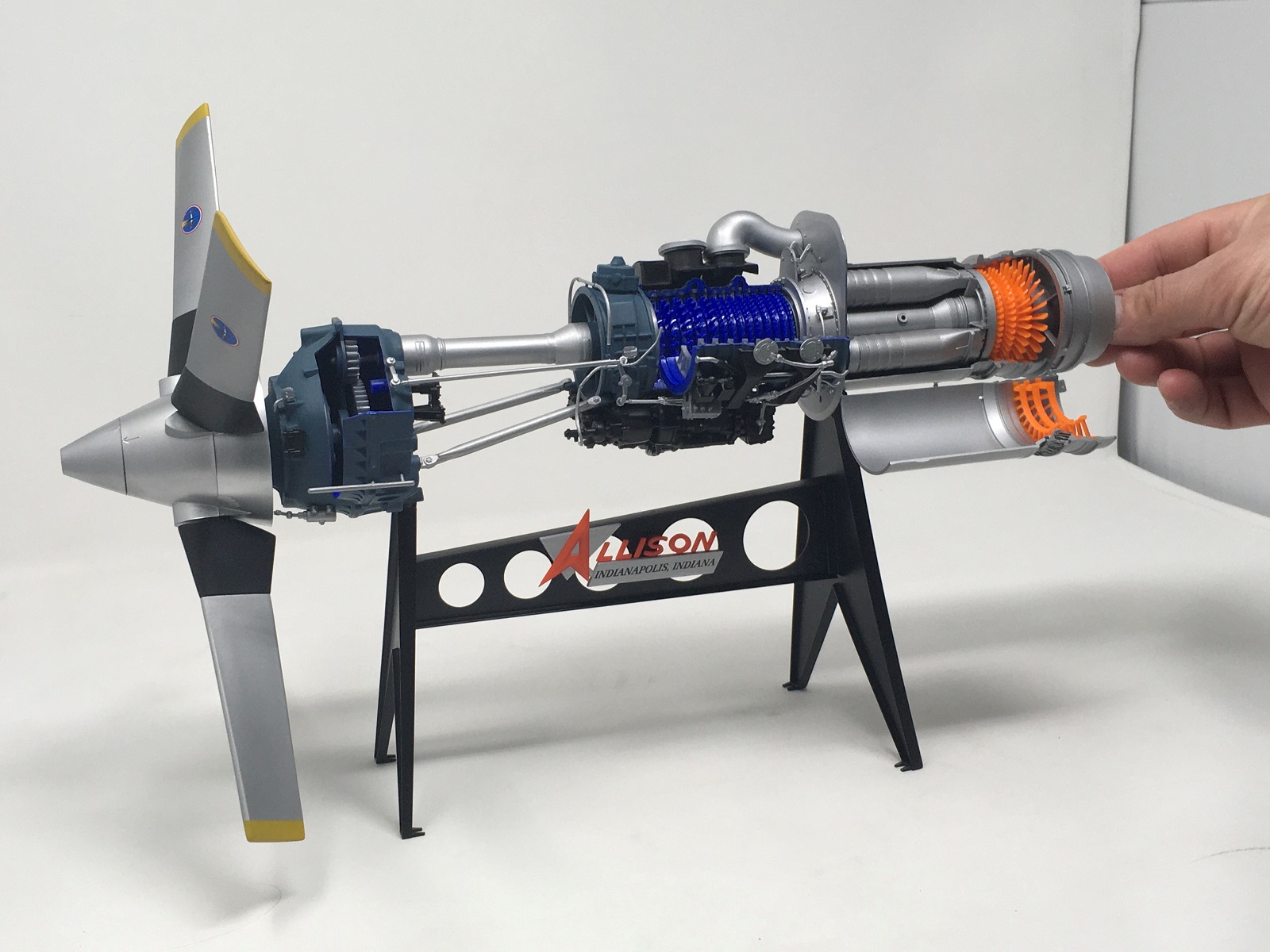
Allison Prop Jet 501-D13 Engine
Following the changes with Revell USA over the last few years, Atlantis Model Co. has acquired molds of classic Revell and Monogram kits. Some have not been released in quite a long time.
The Allison 501 D13 (civilian), or T56 (military) engine entered service in 1954 and is still in production under the Rolls Royce name and designated T56. It was originally developed to power the C-130 Hercules and has since been used in aircraft like the P3-C Orion, Electra, E2C Hawkeye and many others.
I understand Atlantis worked to improve the molds. I could see that the molds in this kit had either held up really well, or had some work done to improve and clean them up.
Atlantis has done a fantastic job taking the modeler back to the 60’s when the 1/10th scale Allison was originally produced in four colors – black, blue, orange and silver. There is an educational booklet and a two-color instruction manual that is a technical resource in its own right. The decal sheet is glossy and in register.
The top opening box was made of fairly thin cardboard, but it was strong enough. The lid contains the same period picture of a young bloke from the 60’s rotating the knob that turns the engine.
I found that studying the instruction manual prior to starting the build was important to plan building and any painting of the model. It also named each part with what the part was on the actual engine. I initially had the absurd idea of building this completely out of the box and not painting it. What was I thinking? I can’t build anything out of the box!!! I did succeed to a degree and left some parts unpainted.
As I removed parts from the sprue it was apparent that mold seams and sprue attachment removal and clean up would mar the plastic surface somewhat and be visible on the finished unpainted model. This is not to say that it couldn’t be built out of the box and produce a great looking replica. The plastic was easy to sand. Some parts, like the stand, exhibited quite large mold seams, while others like the numerous pipes had very petite mold seams.
I assembled what I could and then began a long process of removing each part I intended to paint, attaching it to a toothpick and labeled it with its part number. I did not paint any rotating parts like cogs, gears, shafts or turbine and compressor blades.
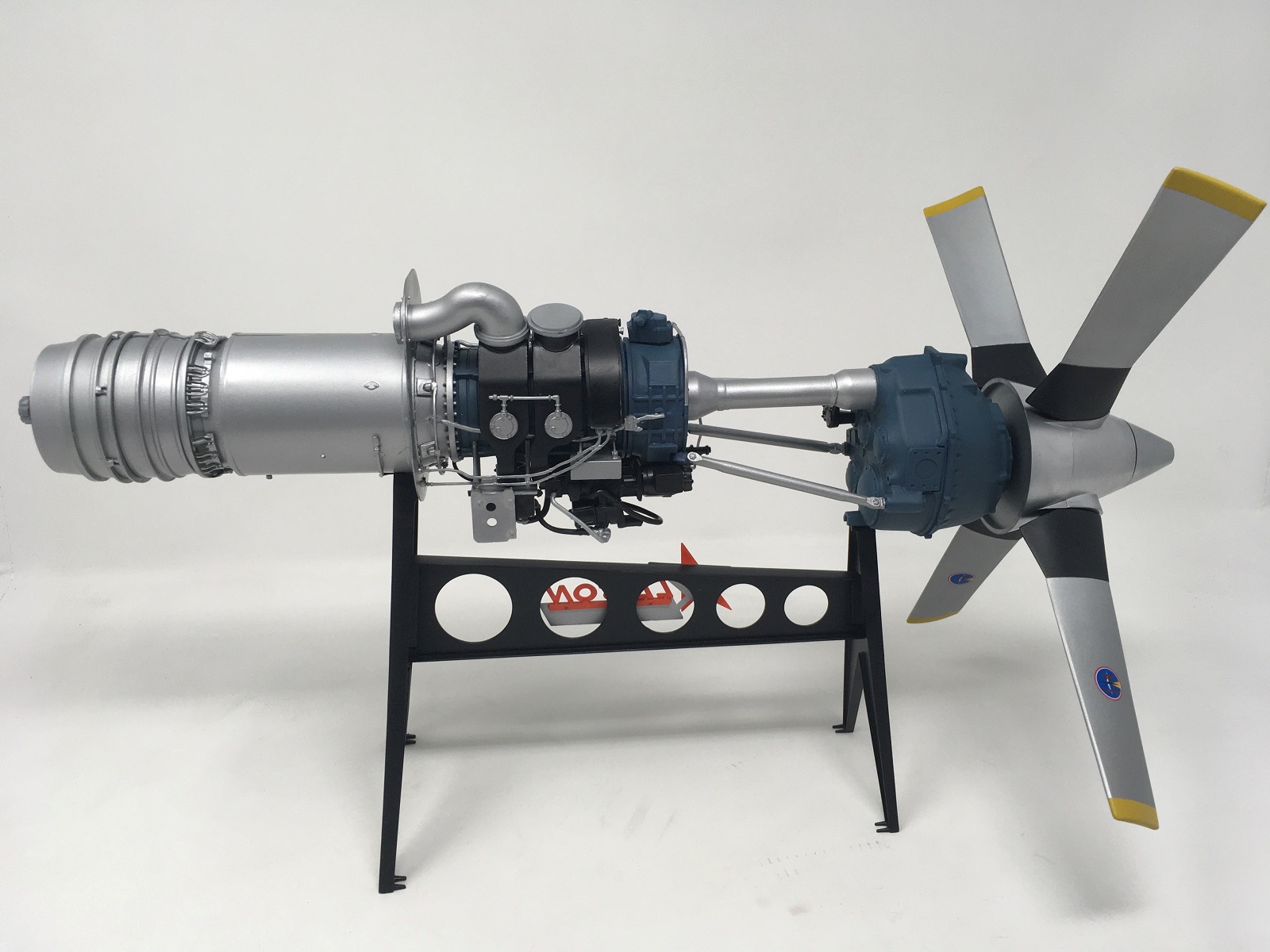
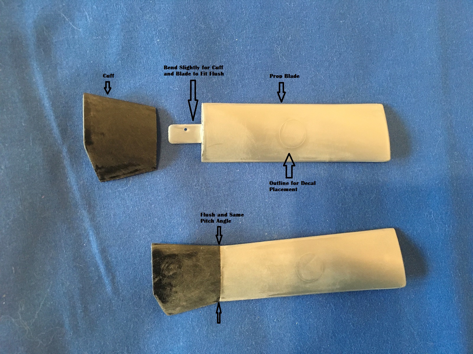
The four propeller blades were assembled. I had to bend the tab at the bottom of each blade that slotted into the top of the cuff so the prop blade and cuff pitch angle lined up flush. As with many “vintage” kits, raised circles are present on the prop blades to show where the Aero Products decal fits. I sanded them down until they were just visible. Having the raised circles really made it painless to apply the decals in the correct place.
I found the turbine coupling shaft that ran through the “hot section” where the exhaust, turbine blades and combustion chambers were located, was bent at about a 45 degree angle. I don’t know how it became bent, but when I tried to straighten it, it broke. I drilled holes in each part, inserted a length of wire and mated the two sides with plenty of super glue. I hope it’s strong enough as this will not be accessible when completed. I looked at other reviews online and didn’t see any damage, so I’m not sure what happened here. The turbine blade disks were glued to the repaired shaft and the exhaust pipe and housing was glued together. Everything rotated nicely here. The turbine blades had a little flash that needed removing.
Six combustion chambers were glued together. The fit was fine and seam cleanup was painless. Remember that one is removable.
Most painting was done with Model Master Enamel. The silver parts were painted aluminum and the black parts painted with semi-gloss black. I used Tamiya medium sea blue for the blue outsides of the reduction gear casings and compressor chamber. The insides were left unpainted, as were the blue compressor blades and the silver guide vanes in the “cold“ section. I liked the bright blue of the plastic. The turbine blades and turbine guide vanes were left unpainted in their orange plastic for some contrast and to represent the engine “hot” section.
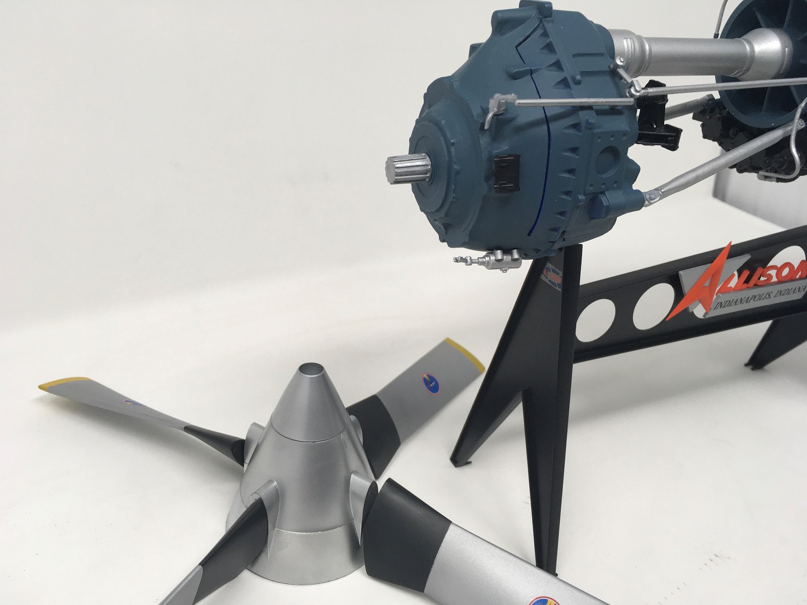
The propeller blades were painted aluminum with yellow tips and the cuffs painted matt black. I debated whether to paint the spinner aluminum to represent a civilian airliner version, or matt black for a T56 military version. I went with civil and used Model Master enamel chrome that gave a nice polished finish.
With everything painted, assembly commenced again at a fast pace. I followed the instructions to make sure everything went together correctly. Most parts fit very well and was a tribute to the age and quality of this model! In areas where there was rotation, I applied a layer of Super Lube.
The thirteen blue compressor blade disks were glued to the rotor drum to form the rotating compressor section. Most disks had some flash that needed removing. Thirteen inlet compressor guide vanes attach in slots in the compressor casing. They were “keyed” so they only fit one way. These had quite a lot of flash and remnants of ejector pin marks. A quick swipe with a knife sorted these out. Most of the guide vanes are not visible anyway, but it is important to have a smooth surface for the compressor blades to pass without interference. Make sure the guide vanes are flush with the edge of the cut away part of the casing, otherwise the “viewing” door won’t close properly.
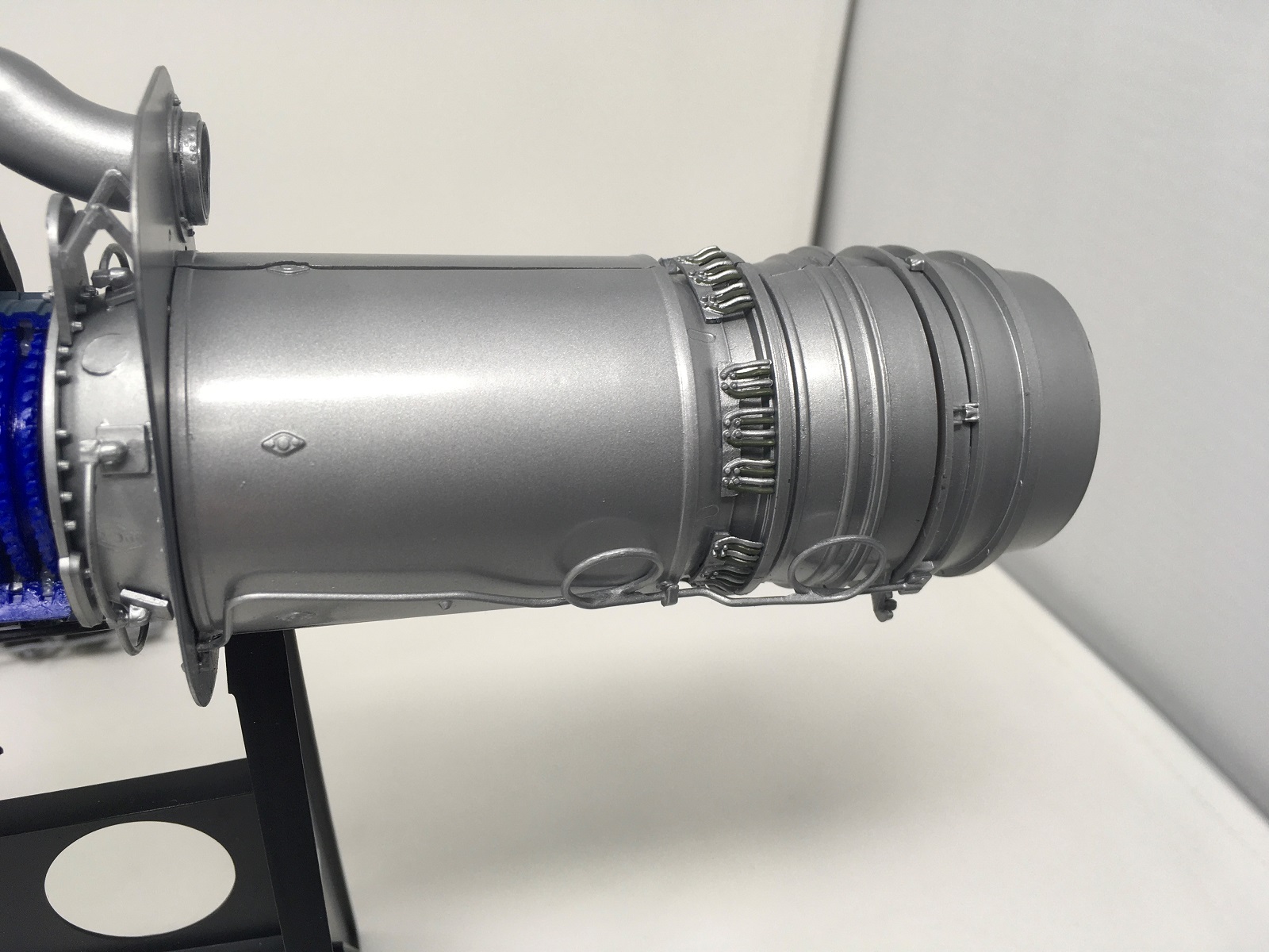
The compressor casing was next. I installed the compressor disk/drum assembly, end guide vanes, air inlet housing, rotor bearing plate and compressor diffuser and spray shield. While I applied plenty of Super Lube, I could not get the compressor blades to rotate freely. I never figured it out, so the engine needs help rotating!
I assembled the reduction gear casing, installing all the working parts (planetary cogs, pinion wheels and shafts) and plenty of lube. Attaching the door was an exercise in “delicate brute force” to get the hinge stub in place without breaking it. I split the plastic a little in the process, but it was returned to normal and I applied a little super glue along the split which cannot be seen. Everything in this assembly works well.
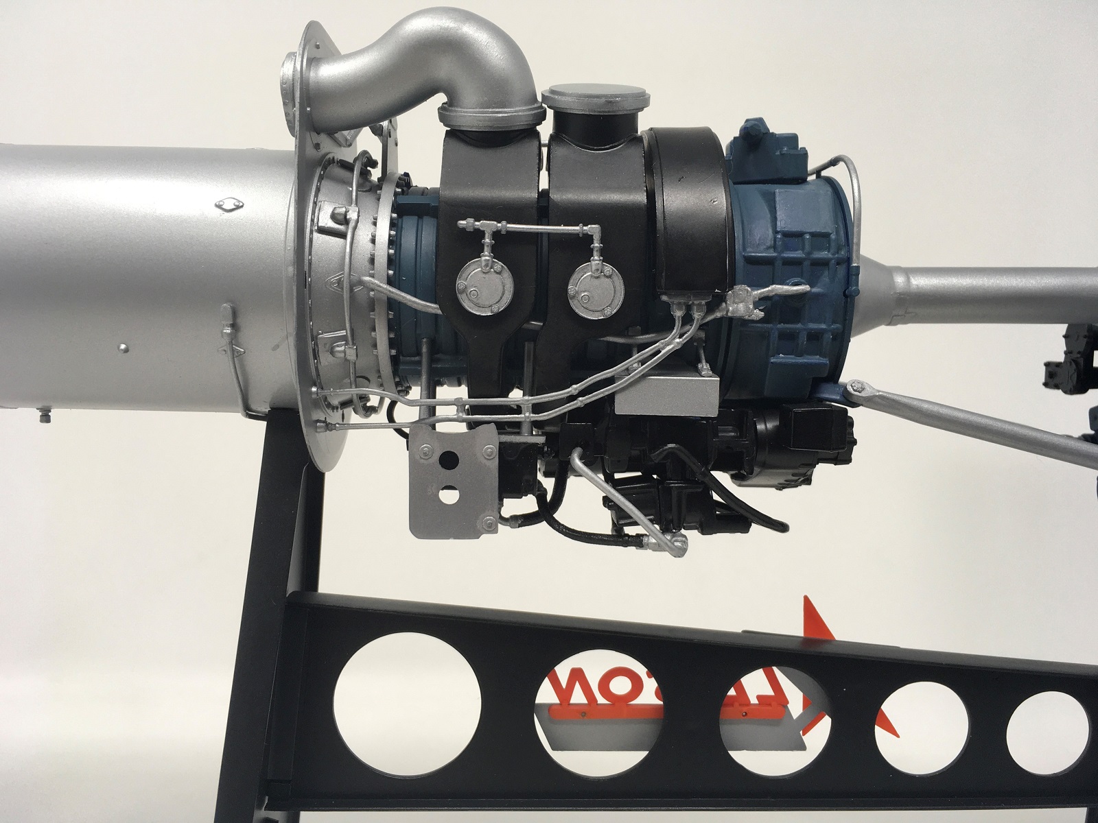
The most confusing and ambiguous part of the build was attaching the multitude of pipes and hoses around and under the compressor housing. While the instructions did a fair job of showing where they belong, there were very few positive attachment points, leaving you to guess where to glue them. I could figure out the starting point of most of the black hoses underneath and around the accessories assembly, but I had no clue as to where they were meant to finish. The only consolation is that when the model is on the stand you can’t see the hoses that go “nowhere”.
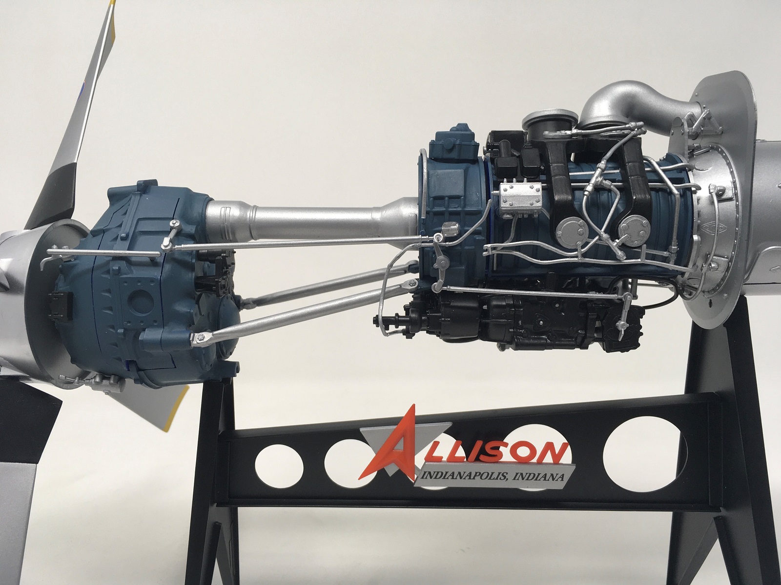
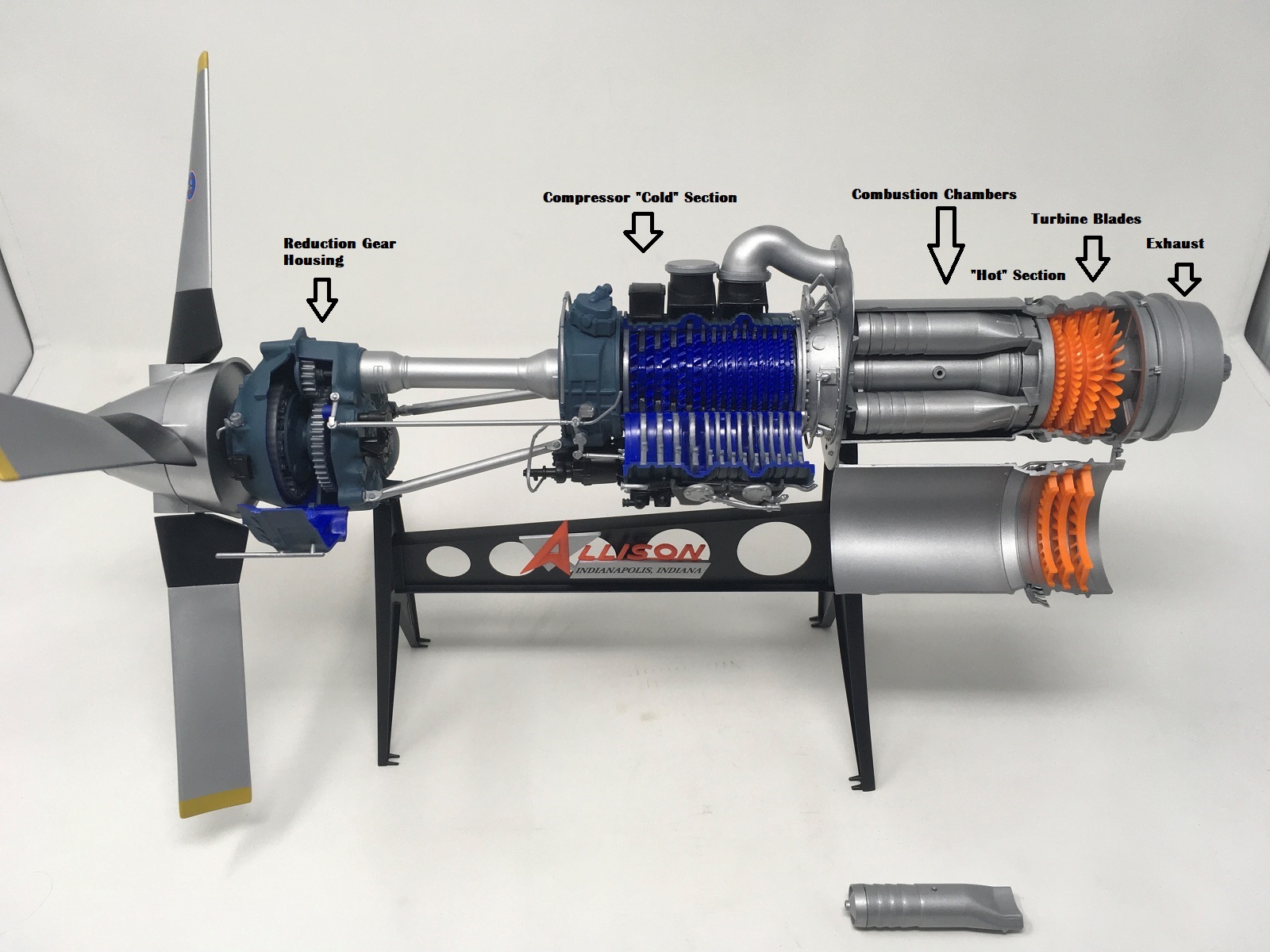
Once all the hoses, pipes and other accessories were added, the reduction gear housing, compressor and turbine/exhaust sections were brought together to form an Allison Turbo Prop engine. Each section contained a shaft that was connected to the next with a coupling. Two support arms attach from the reduction gear housing to the compressor inlet housing to add rigidity and torsional (rotation) support.
The stand was built and painted Model Master semi-gloss black. Quite large mold seam lines were sanded off the outside edges of the stand parts. The data plate decal was applied and fit perfectly in the raised outline. I sprayed the “Allison” letters orange after sanding ejector pin marks from the front of some of the letters. The backing name plates were sprayed aluminum. The orange name really looked great against the aluminum and black colors. The engine was mounted onto the stand, followed by installing the compressor chamber and turbine/combustion chamber cutaway “doors” to complete assembly.
It was time to start making turbo prop whirring and whining noises and changing the pitch of the propeller!!! In the end I got the engine to rotate somewhat freely after much rotation and wearing it in.
I really enjoyed building this piece of nostalgia and I learnt a lot about the engine and its components. It was originally designed from the actual engine specs and appears very accurate. I would recommend the kit to modelers with at least some experience and the ability to read and follow the instructions. The ambiguity of fitting the pipes and hoses will test even experienced modelers. At least it did me!!
My sincere thanks to Atlantis and the IPMS for the opportunity to build and review this great model.

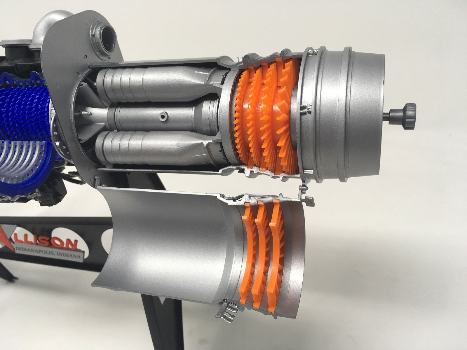
Allison Combustion Chambers (One Removable), Turbine Blades and Guide Vanes
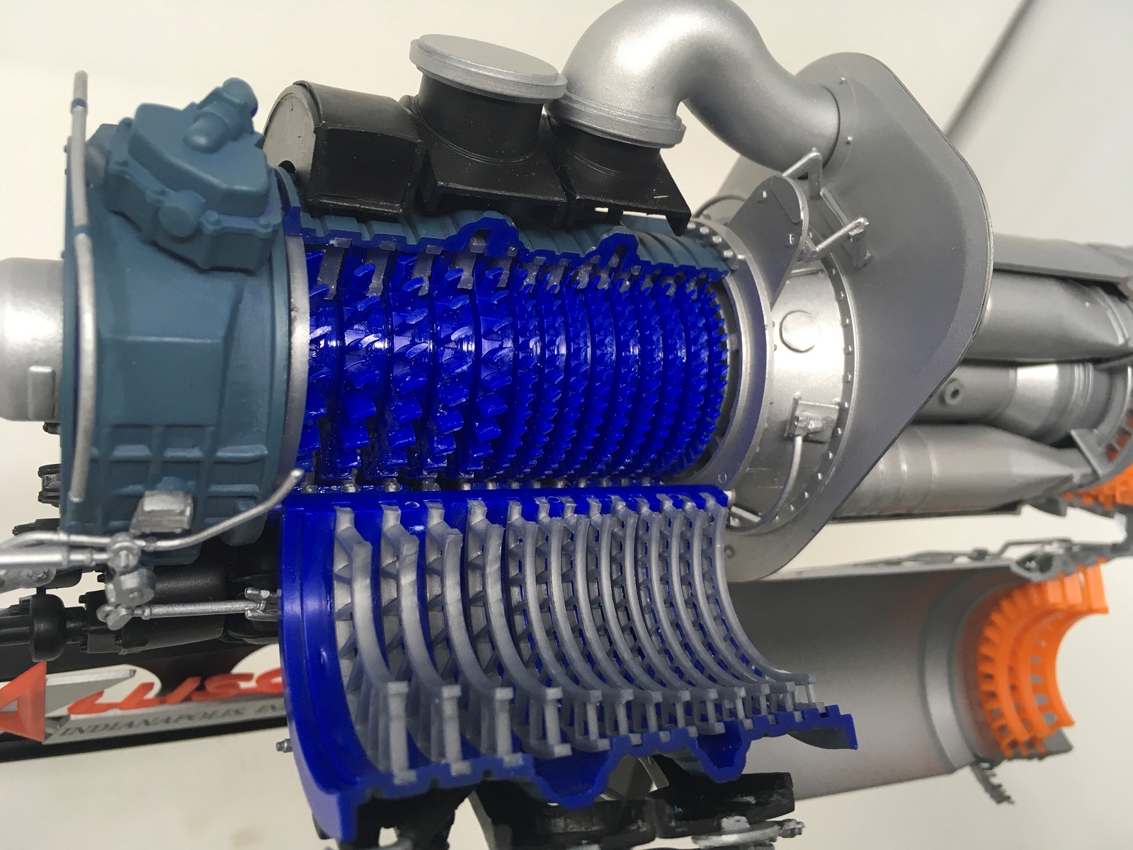
Allison Compressor Blades and Guide Vanes
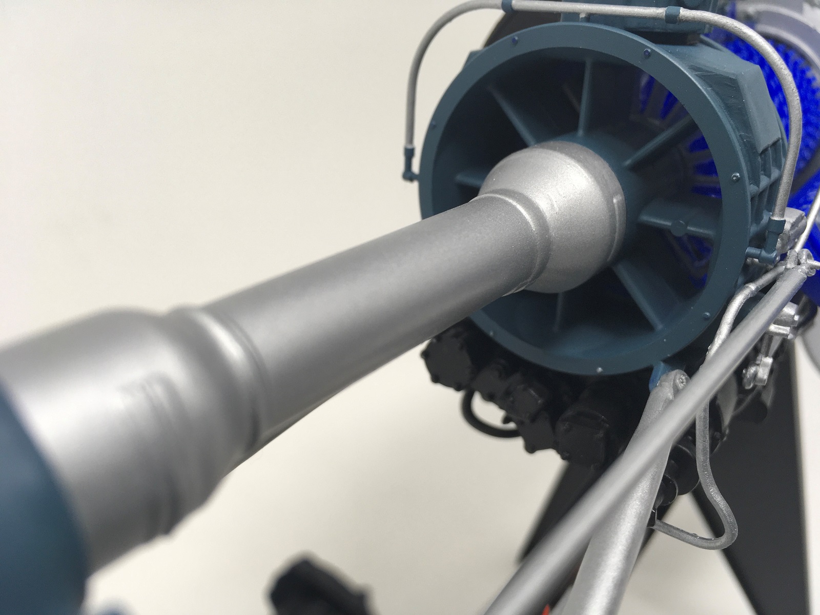
Allison Comressor Air Inlet
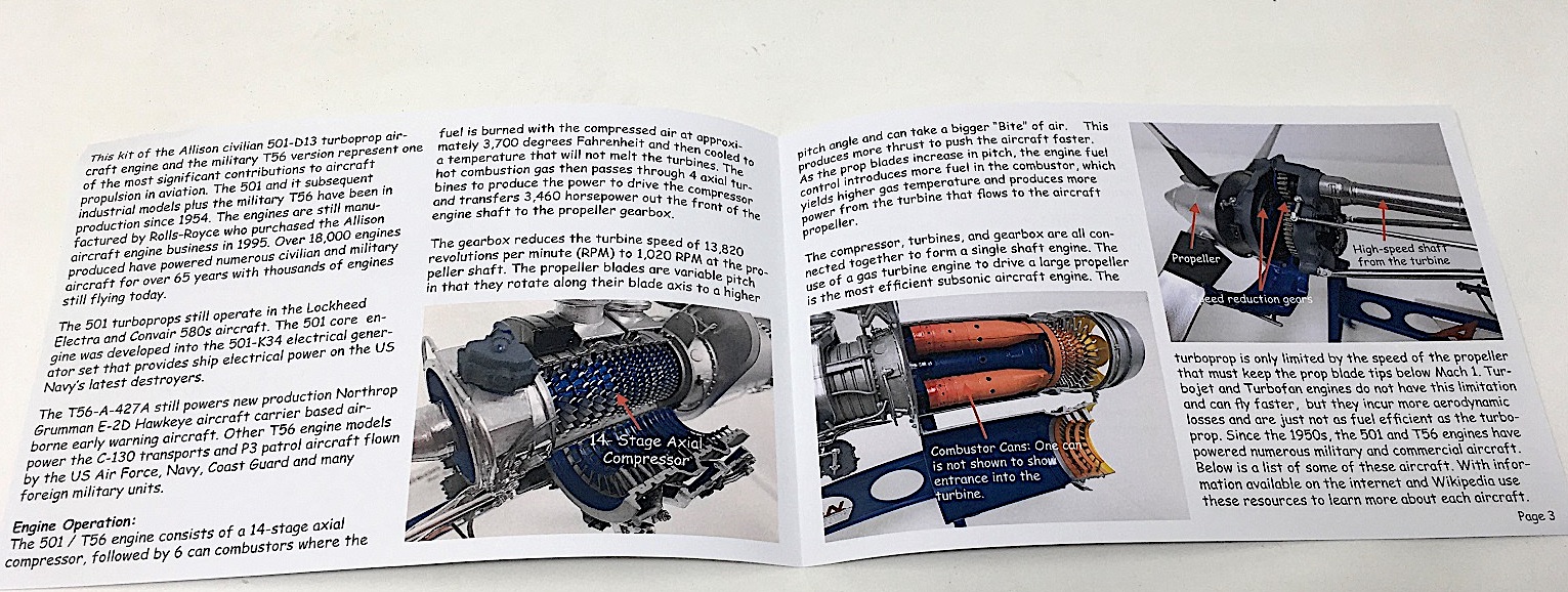
Allison Educational Brochure 1

Allison Exhaust and Operating Wheel

Allison Front

Allison Instruction Manual
Allison Left Side Compressor Housing and Reduction Gear Casing
Allison Left Side Exposed
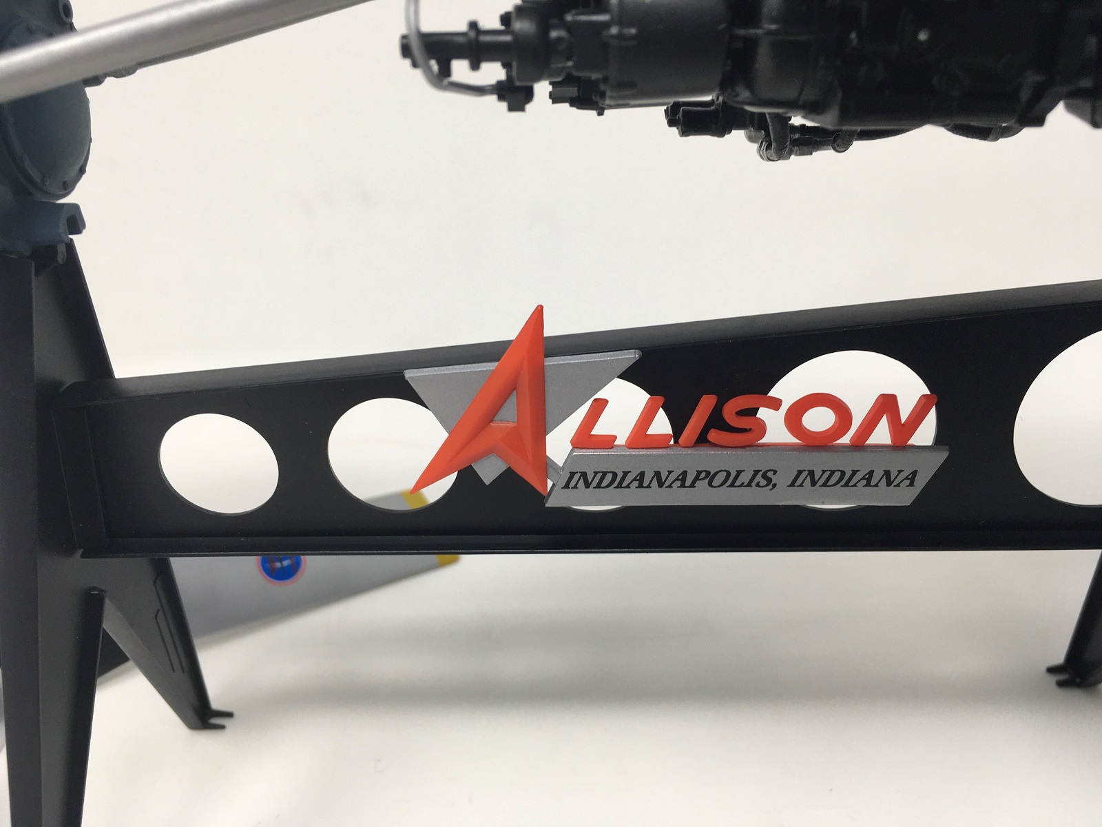
Allison Name Plate
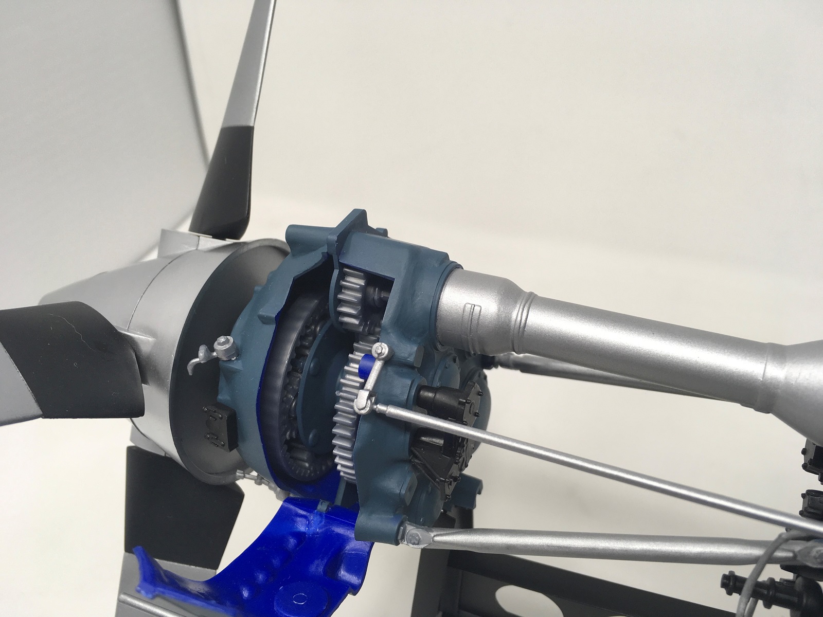
Allison Reduction Gear Internals & Planetary Gears
Allison Right Side Comressor Housing
Allison Right View
Allison Turbine, Combustion Casing (Hot Section)
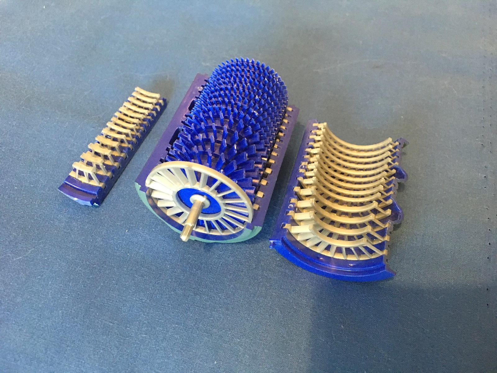
Compressor and Stator Guide Vanes
Operating Allison Engine
Prop Blade Correction
Comments
Add new comment
This site is protected by reCAPTCHA and the Google Privacy Policy and Terms of Service apply.
Similar Reviews