
AH-1Z Viper
Having flown the AH-1G, Q, Mod S, Prod S and Prod S (ECAS) while on active duty with the U.S. Army, I am always drawn to any version of the AH-1. It is truly an exciting aircraft to fly and it just looks plain wicked! The aircraft has been around since 1966 and the AH-1Z is the latest incarnation of that airframe, and tends to make you think it’s going to be around much longer, still. And Kitty Hawk has done a great job of presenting us with a detailed model of the Marines’ newest helicopter. And, our very own Floyd Werner was involved in the design and production of this kit from the very beginning. Thanks go to Floyd for all of his time and efforts to produce this kit. Now, if he can just convince them to do a G Model or F model in 1/48 or 1/35, we’ll be on a roll.
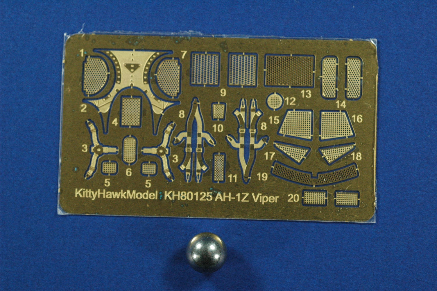
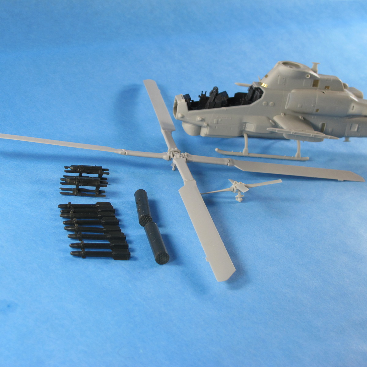
When you open the box, you find five gray sprues which contain 219 parts and a small cardboard box that contains the clear sprue of 13 parts, two decal sheets, a small photo etch fret and a ball bearing nose weight. The eighteen page instruction booklet is 9” x 10 ¼” and another 8 1/4” x 11 ¼” full color painting and marking guide is included. The additional painting guide is the same the stencil placement guide on pages 15 and 16.
For a new kit, I was surprised at the amount of flash that was on some of the parts. There were also some parts that the molds were clearly misaligned due to large steps in the mold joins. In talking with Floyd Werner, he did not have that experience with his sample. There were many ejector pins and ejector pin marks that had to be cleaned up before assembly. I also found some of the join-surfaces to be rounded, also, which required a smear of filler on the join to either flatten or fill the resulting dip. Generally, throughout the assembly, fit was very good. Other than stated above, no filler was used.
The instruction book is very detailed and has many blowups of multiple part assemblies. Color callouts are not consistent, however, so you have to do some research and reference gathering before you get too far. And, if you have good references, you will find that they disagree with the kits color callouts in several areas. Their painting guides disagree with themselves, even to listing two different grays for the same area. Once again, check your references.
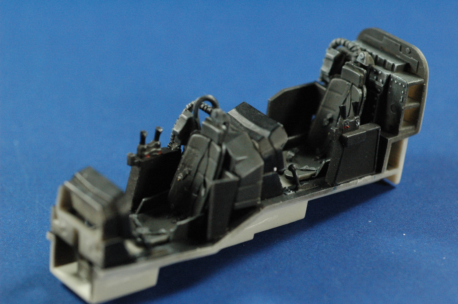
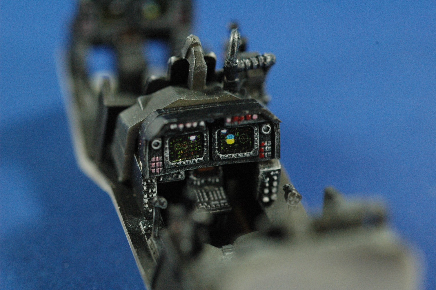
In the first step, which is assembly of the pilot and gunner seats and placement of the seat belts and shoulder harness. The instructions refer to the photo etch belts as decals. but since there are none, it’s not hard to figure out. Annealing the photo etch belts helps immensely in their placement. Everything fits well in the cockpit, but you have to guess at some of the angles, such as the seats. Decals are provided for the instrument panels, but not the side consoles. I opted to paint the majority of the instruments. I did use the CRT display decals, but they were much larger than the relief detail. Everything in the cockpit is in a shade of black, except for the floor, so some judicious dry brushing is needed to bring out the detail. Once it is done, it is a nice assembly. The completed assembly fits perfectly in either fuselage half, but there are no alignment steps or guides to make it easy.
The kit gives you the capability of displaying the engine cowlings in the open position, and the General Electric T700 engines provided are nicely detailed. However, as I was dry fitting everything beforehand, I could not get the forward and aft bulkheads aligned to my satisfaction so they looked right with the cowlings open. So, I opted to close the cowlings. Regardless of which way you go, you have to use the two bulkheads, because they are the anchor points for the upper and lower cowlings. To aid in alignment and attachment, I added strip plastic to the inside of the cowlings. In the end, these gave a lot of strength to the cowling area, as well. I also had fits getting part D50, the bulkhead right behind the turret, to fit. Once I remove the positioning tab, it fit just fine. When you join the forward fuselage halves, there are some small gaps that pressure from some clamps took care of during the glue curing time.
In step 7 you have a couple of decisions to make. As I said, there are forward fuselage halves and there are tail boom halves. This is because the same tail boom is used on the UH-1Z also, which Kitty Hawk has also released. Do not glue the tail boom halves to the forward fuselage halves. You will find later that the fit of the two assemblies is very good and secure. The other decision is whether or not to install the rotor swashplate, part D27. If you do, you will have some fits later trying to insert and align the four pitch change links to the main rotor hub. I opted to leave it off until later. I’m glad I did.
Nearly all of the screens on this kit are photo etch parts, and they all fit very nicely in their designated recesses. I have to admit I was pleasantly surprised. I do regret, however that I did not think about spraying the entire insides of the forward fuselage halves and the tail boom halves flat black. It would have helped with some optical illusions later, instead of having a clear view all the way through.
There are several external scoops that require careful study of the painting guides and references to make sure they are oriented properly. The engine intake inlets suffer from some very prominent ejector pins and pin marks that must be cleaned up, as they are clearly visible when looking in the front of the inlets. The seams have to be cleaned up, as well, which ends up being a chore, but a necessary one.
Step 9 is the assembly of the turret, and this is where that large steel bearing comes into play. It is captured inside parts C30 and D49, the turret halves. Unfortunately, the turret is not accurate. There is no bottom to the turret, as the kit depicts. It is open, exposing the gun mechanism. The M197 20mm Gatling gun barrels are very nicely done.
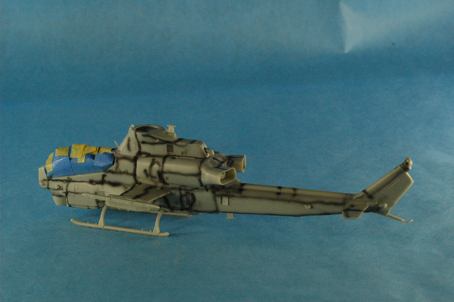
Step 10 is the assembly of the FLIR globe, which is composed of two clear parts which has four lenses on it. Having Eduard’s mask set here is a great asset in masking. I never could figure out what was the proper color to use for the lenses, or whether to just leave them clear. I ended up painting the ball clear blue, then masked the lenses before painting the ball FS36375. The ball is then captured in between the two nose halves so it is free to rotate.
Steps 11 and 12 are the attachment of more external parts to the fuselage assembly as well as the skids. Pay careful attention to the parts for the skids, because they are not interchangeable. This is also where you attached the engine cowlings, which the instructions show them closed. No mention or illustration anywhere of them being open. Maybe I wasn’t supposed to display them open in the first place. Before you glue the skids to the fuselage, take a close look at the aircraft you are going to depict. Some AH-1Z have black non-skid areas painted on the skids and some do not. Believe me, painting the skids before attachment is much easier than doing it later. More on pre-painting to follow. Step 12 is also when you close the ammo bays. Yes, there is some nice detail inside the bays, which you put in during Step 11. Being afraid of a tail sitter, I had intended to close mine from the very beginning, so I could add some BB’s throughout the bays for some more forward ballast. I added enough weight, but not enough epoxy to hold them, because I have a loose BB inside the nose now. Also, not indicated is the pipe assembled with parts B29 and B30 should be a bronze or jet exhaust color. I did not catch that until after the model was completely painted and decaled. It was fun trying to mask it afterwards. The same goes for parts C25 and C26 in Step 15. These are exhaust color, also. Those I did catch.
Steps 13 and 14 deal with the stub wings assembly. Here it shows you making holes in the bottom of the wings. Before you do, decide what weapons load you are going to use on your Cobra, because these holes may not be the ones you want. You will also find in looking at various reference, the weapons loads may not be symmetrical. The photos on the Werner’s Wings decal instruct sheet show two non-symmetrical examples. When you have the wings assembled, this is the second time that you need to pre-paint. The wings have very large non-skid painted surfaces that are almost impossible to mask and paint after the wings are glued to the fuselage. Take my word for it; I know. I left off all of the clear parts until after the model was completely painted.
In Step 16, you install both of the left side canopies, but at no time do the instructions show the installation of the right side canopies. The gunner and pilot canopies are clearly intended to be open due to the tabs on them and the corresponding slots on the center canopy. I left off the air data sensor and mast, as well as the pitot tube because I knew I would knock both of them off I did put them on. This is also where the instructions have you glue the wings on.
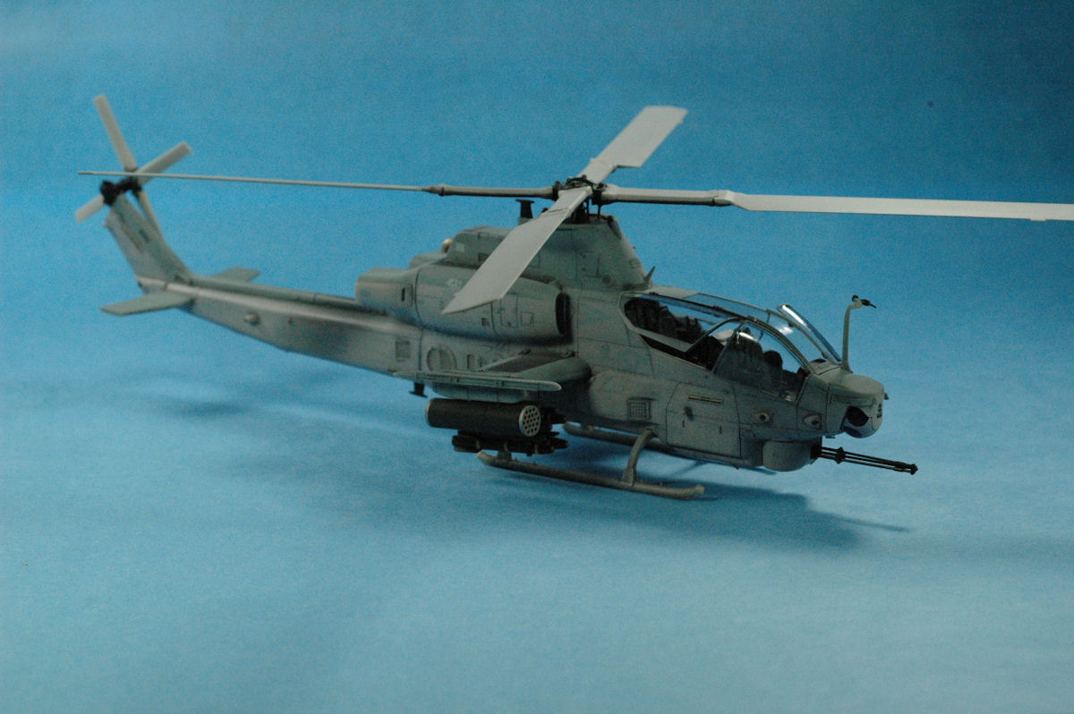
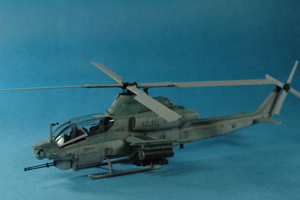
I particularly like the way Kitty Hawk designed the rotor systems. The hub also has inserts for each of the blades, which are captures between the blade grips. This prevents the ever-present hub droop of rotor blades on most model helicopters. There are some sink marks on the lade hubs, but these are easily filled and smoothed over. Joining of the pitch change links is another story. Even after studying pictures of the AH-1Z rotor head and the kit parts, I never really figured out just how they were supposed to be assembled. Surprisingly, they are fragile, too, as I broke two of them and never found part of one of them. Painting the rotor blades is a masking task, also, as the leading edges of the blades are either gray or silver and the undersides are black. The rotor hub is also black. I did a lot of freehand painting in this area. The tail rotor gear box and rotor disk assembly also require some judicious masking or pre-painting as they are gray and black also. The painting of the main rotor shown on the painting guide does not match any of my references.
Step 19 would have you glue the tail rotor to the tail rotor gear box, but I would leave it off because it will get in the way of painting and decaling. They also show gluing part C12 in place. I would hold off until the tail boom has been glued, in Step 20. You also attach photo etch part PE2 in Step 20, and I would attach it prior to the tail boom, because there are some subtle curves to the mating surface. As I stated before, the tail boom went on with no problems and was a positive fit with no alignment problems. Part C12 was then secured in place. Leave off the main rotor until everything else is done. It will just get in the way. Even in the end, I did not secure mine with glue.
Steps 21 through 25 involve the weapons stores. This was the most disappointing part of the entire build. Not much of anything fit, without a lot of work. The Hellfire launchers were particularly difficult to assemble without Superglue. The shape of the Hellfire’s is questionable, as well. The warhead nose should be clear and the shape is much too tapered. The launchers have very tiny tabs on which to locate the very small and shallow recesses in the missiles. Superglue and a lot of patience is required to hang the Hellfire’s. The supports for the rocket pods are questionable, as well.
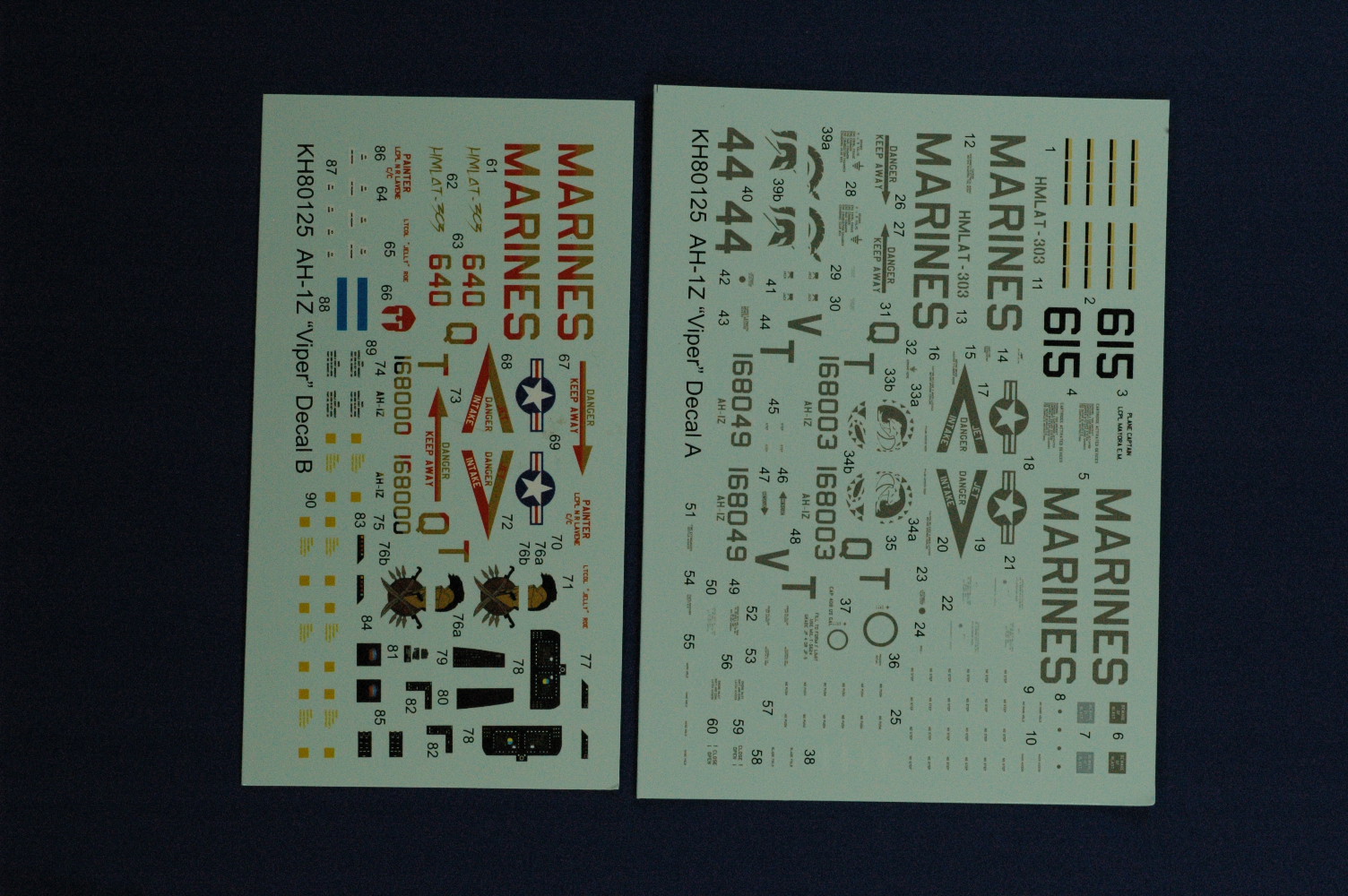
The kit provides markings for two aircraft; No. 615 of the HMLAT-303 and the rather garish red, black and gray No. 640 of HMLAT-303. Since I was to review Werner’s Wings Viper sheet, the only kit decals I used were some of the stencil markings and the markings for the Hellfire missiles. The instructions would have you paint the Hellfire’s olive green, but everything I found said black. However, before I painted them black, I tried the kit stencils for them. When I applied decal #90, which is yellow, it completely disappeared. It was so transparent that the green showed right through. After they were painted black I did not have much more success. So, in a panic, I contacted Joseph Osborne of Fireball Modelworks for his missile marking sheet, which is great. The kit stencils that I did use all laid down nicely with no silvering.
The kit clear parts for the canopy are very thin and very clear. They also fit extremely well for separate parts.
A lot of things that other kit manufacturers would include in the molding process, such as sensors, inlets, vents, antennas etc. Kitty Hawk has chosen to do as separate parts. Maybe a little fiddly, but they all worked out nicely and were closer to scale. Their photo etch screens were a very nice touch. Plus, I wasn’t breaking off antennas all the time. The kit was an enjoyable build and the Werner’s Wings decals were in keeping with the high quality of all of their decals. I want to thank Kitty Hawk, and IPMS/USA for the opportunity to do this review


Comments
Add new comment
This site is protected by reCAPTCHA and the Google Privacy Policy and Terms of Service apply.
Similar Reviews