
AFV Stryker Dragoon
Brief History from Wikipedia
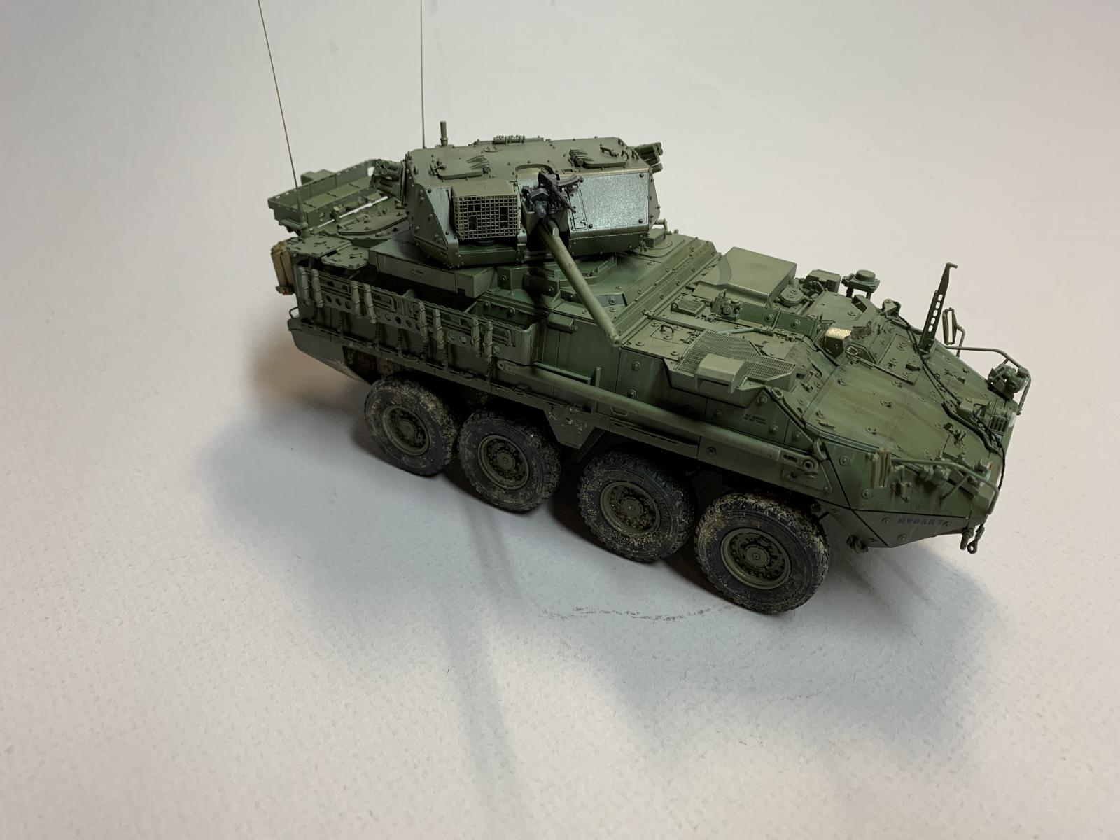
The IAV (Interim Armored Vehicle) Stryker is a family of eight-wheeled armored fighting vehicles derived from the Canadian LAV III. Stryker vehicles are produced by General Dynamics Land Systems Canada for the United Staes Army. It has 4-wheel drive (8×4) and can be switched to all-wheel drive (8×8). The vehicle is named for two unrelated U.S. soldiers who posthumously received the Medal of Honorr: Private First Class Stuart S Stryker, who died in World War II, and Specialist Four Robert F Stryker, who died in the Vietnam War.
In April 2019, the Army decided to add cannon armament to Stryker DVH ICVVA1 vehicles in three brigades; the first is planned to be equipped in 2022
The Kit
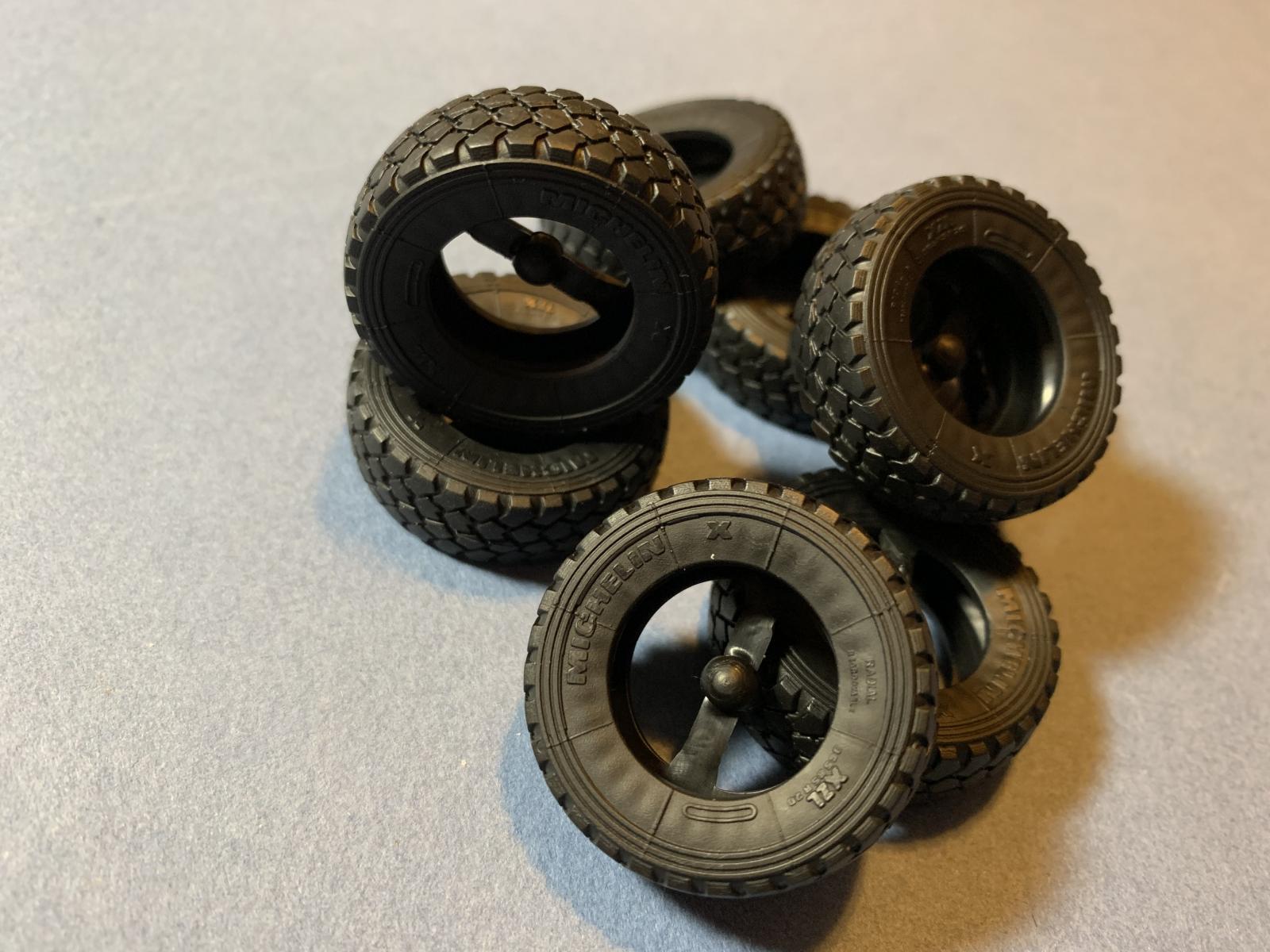
My first step was to inventory the sprues and parts to confirm that everything was included in the box. Each sprue is separately bagged even when two sprue are bagged together. There are 14 sprues, top and bottom hull parts, 8 vinyl tires, two PE frets, two clear parts sprues, 4 stainless steel sleeves, 12 vinyl bushings, two small vinyl parts sprues, a short length of twine and a small decal sheet.
The plastic parts are molded in an olive green plastic. Molding appears chrisp and well detailed. The tires are exceptionally well detailed. Lots of plastic in the box.
The Instructions
The instructions are provided in a 24 page, glossy paper booklet. The first page is a brief description of the vehicle, the second page has a list of paint colors and manufacturers. Pages 3 through 18 cover the assembly shown in isometric line diagrams with part numbers and colors (when appropriate) noted. Page 19 shows the sprue layouts and miscellaneous parts. There is no note for parts not to be used in the build, and there are a few. Pages 20 through 24 are color views of six vehicles all painted field green. This instructions format can become very busy and sometimes confusing, and therefore it is always a good idea to study each current step and the next steps to avoid errors.
Also included was a separate 8" by 12" box art color drawing of a 3/4 front view of the vehicle on a white background. Not only is this suitable for framing if you are so inclined, but the drawing offers some additional detail information.
Construction
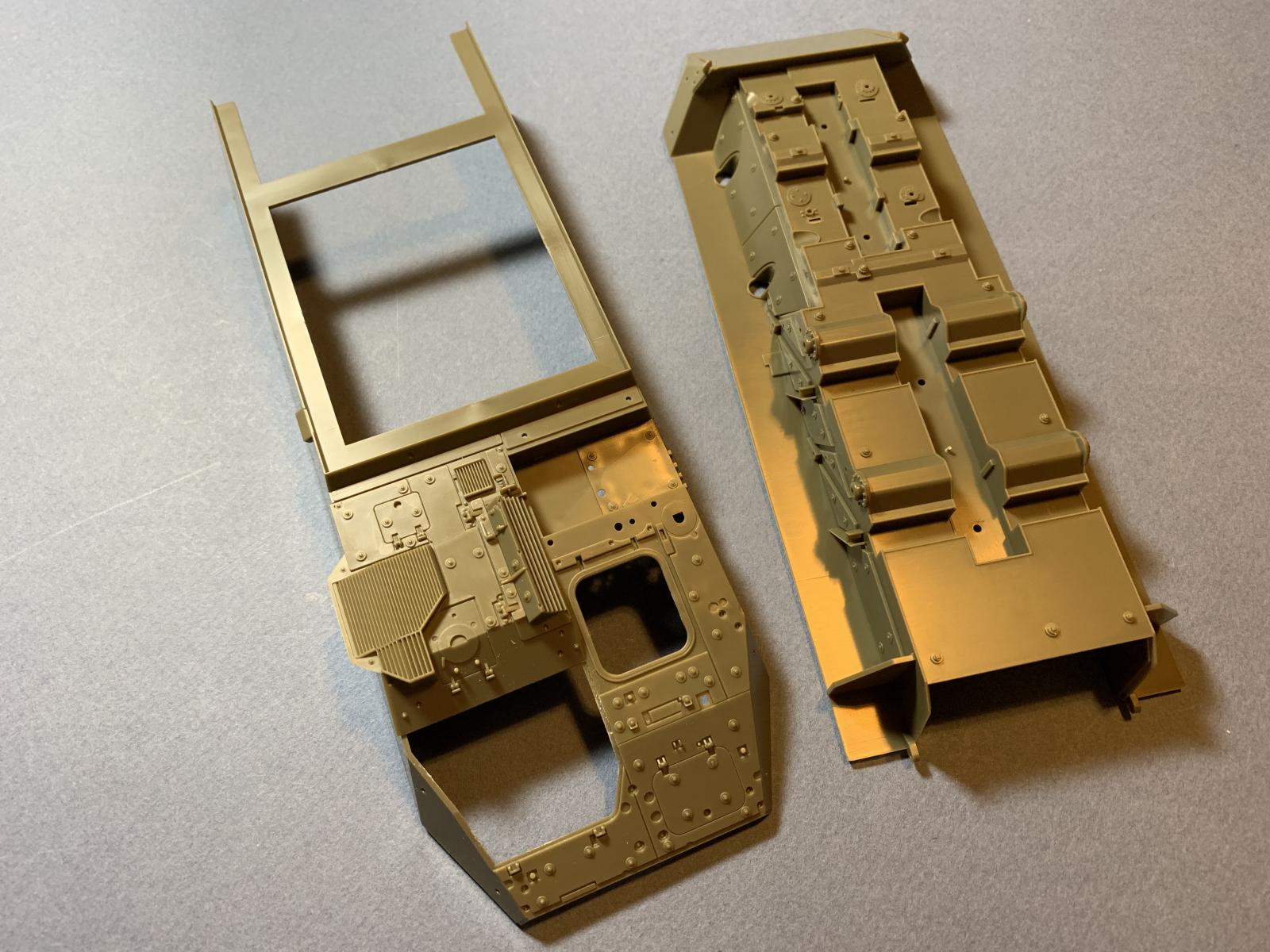
Lower Hull and Suspension
Steps 1 through 11 cover the assembly of the lower hull and suspension system. The assembly starts with the hull bottom. Several molded -on bolts are shown as being removed, and once removed various sized panels are fixed in place. The two pairs of differentials and axels are fitted in place, but may only be oriented in a straight forward aligment. In the event the ambitious modeler wishes to display the model with the wheels turned slightly some surgery and modification of parts is necessary. This would result in a more candid apparance.
As with any multi-wheeled vehicle it is important to make certain the axels and wheel hubs are properly aligned to allow all wheels to touch the surface. There was no issue here as the parts were self-aligning.
In step 8 part Q24 was a bit of a challenge to fit in place on the underside and then glue. The solvent was aplied progressively until the part was fitted in place all around. So far that was the only fit issue.
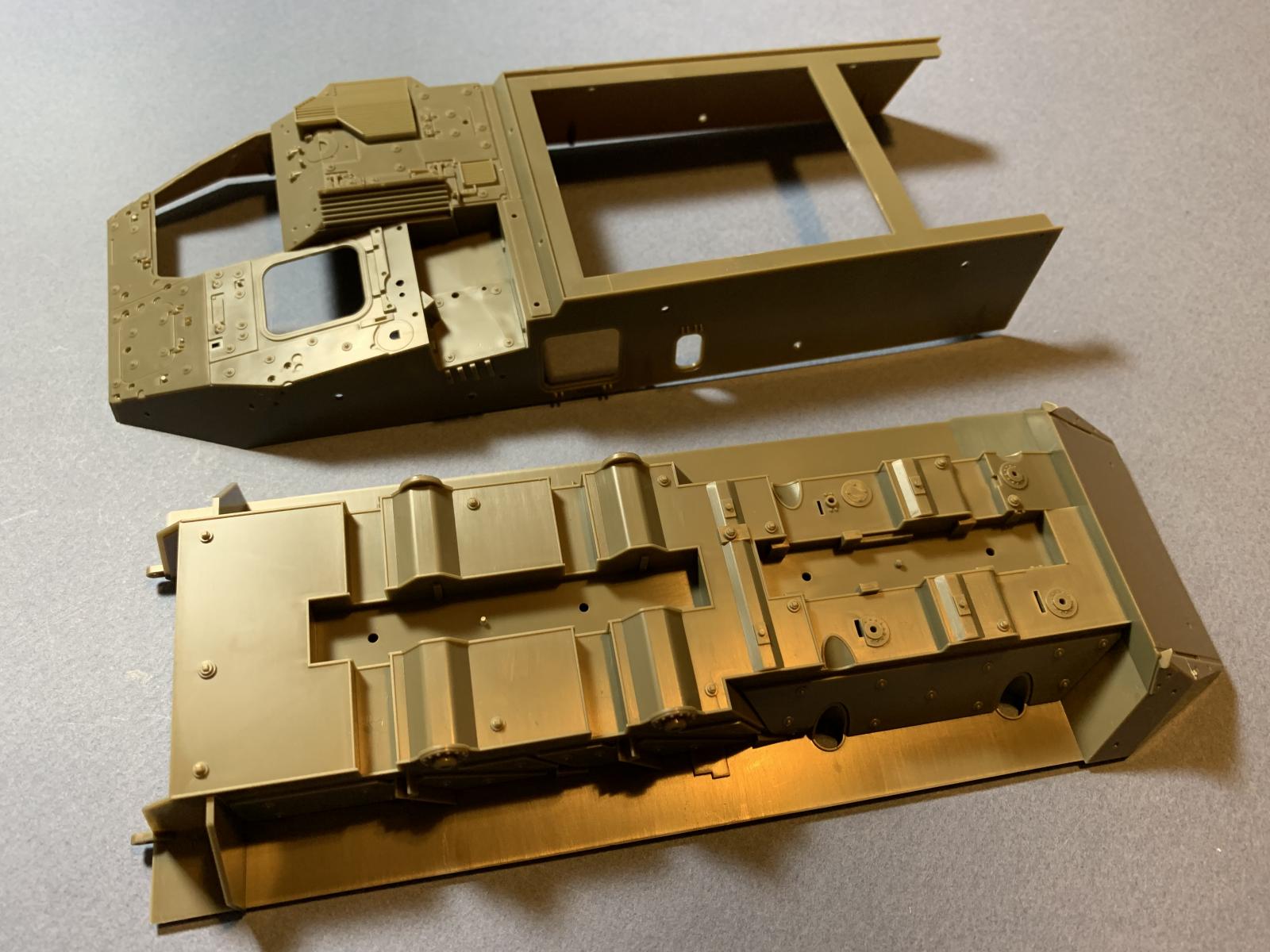
Upper Hull
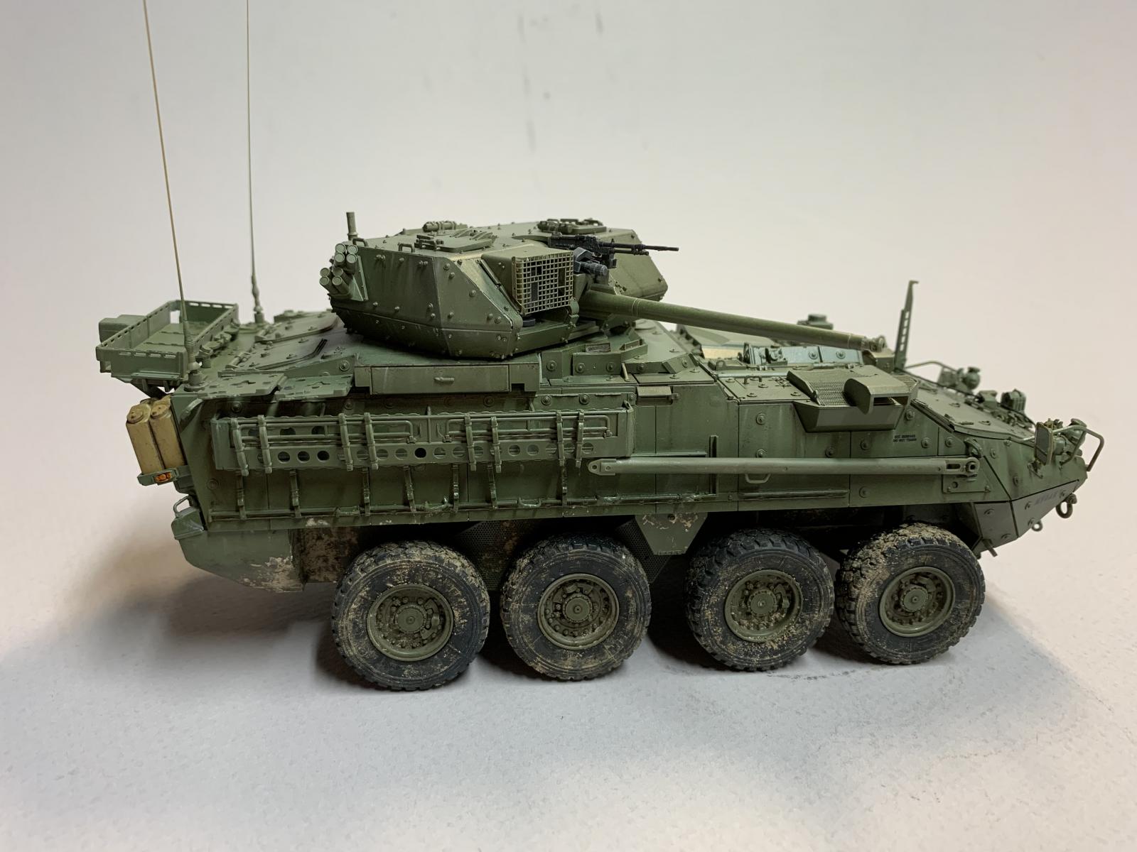
The work on the upper hull begins with the two large bolt-on side armor panels. The kit hand grip parts are nice, but are quite delicate and removing the sprue spur risks breaking the parts. Each side has several equipment straps molded in a stored configuration. There are two types of straps and the instructions are a bit vague on the exact locations. In addition there are two storage troughs on the sides, one per side. Each trough is fitted with two short, horizontal rod-type stiffeners. These were replaced with short lengths of .020" diameter Evergreen rod as the kit parts proved dificult to clean up without breaking the parts.
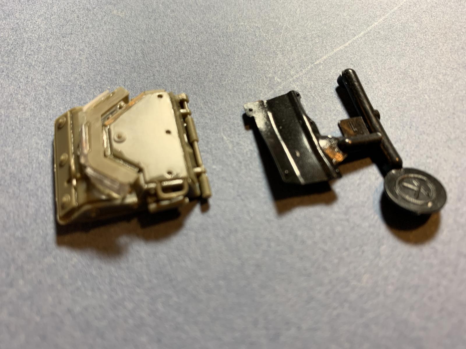
The honeymoon came to an aburpt end with Step 29. This is the assembly of the left front headlight. There are 10 parts involved in this sub-assembly, andthose parts are all small and difficult to handle. One part has no number indicated in the instructions, so I used the process of elimination to hopefully find the correct part. The assembly required a good deal of guesswork and dry fitting (which was difficult given the small size of the many parts) to put everything together. Turning the page to Step 30 we are faced with deja vu: a second headlight assembly with similar issues. Here all the parts are numbered, however the cleanup and assembly is just as challenging at the first headlight. The smallest assemblies offered the biggest challenge.
For some reason a small vinyl part is used on the hinge side of the driver's hatch. I could find no reference images of the real thing, so I was in the dark on what it was. I assumed it was some sort of flexible shield to prevent rain water from running down into the crew compartment when the hatch was opened (???). In any event the part did not fit well and I elected to not use it.
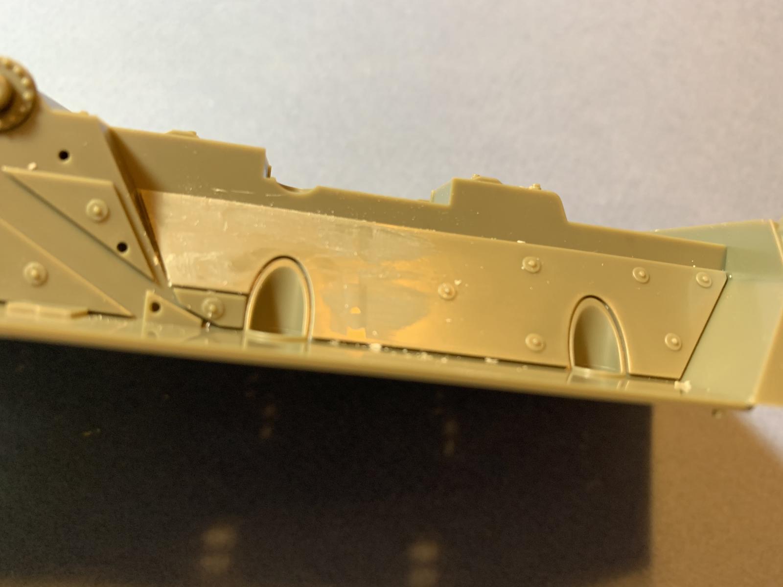
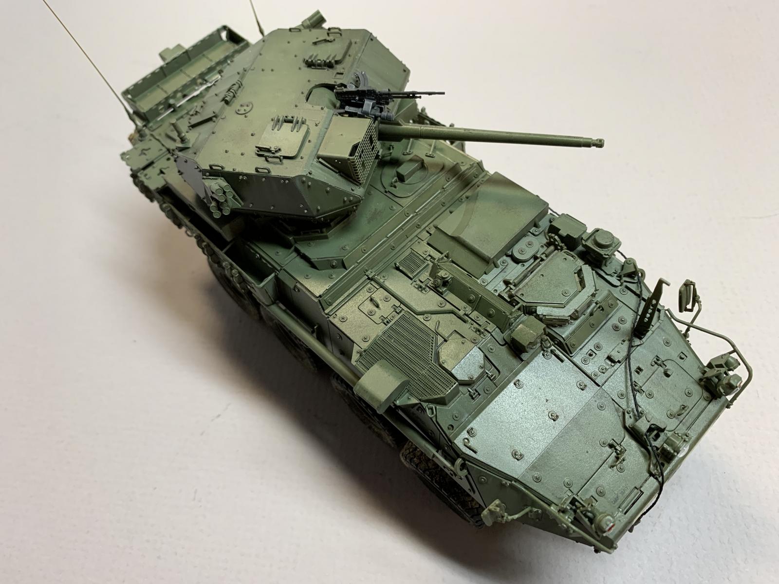
The exterior sides surfaces of the upper hull are literally covered with individual armour plates that are placed individually. The parts fit into place fine, with adjacent parts going into place without issue. There is a lot of plastic involved with this phase. and is completed with multiple steps in the instructions. Follow the steps and test fit each part and there should be no problems.
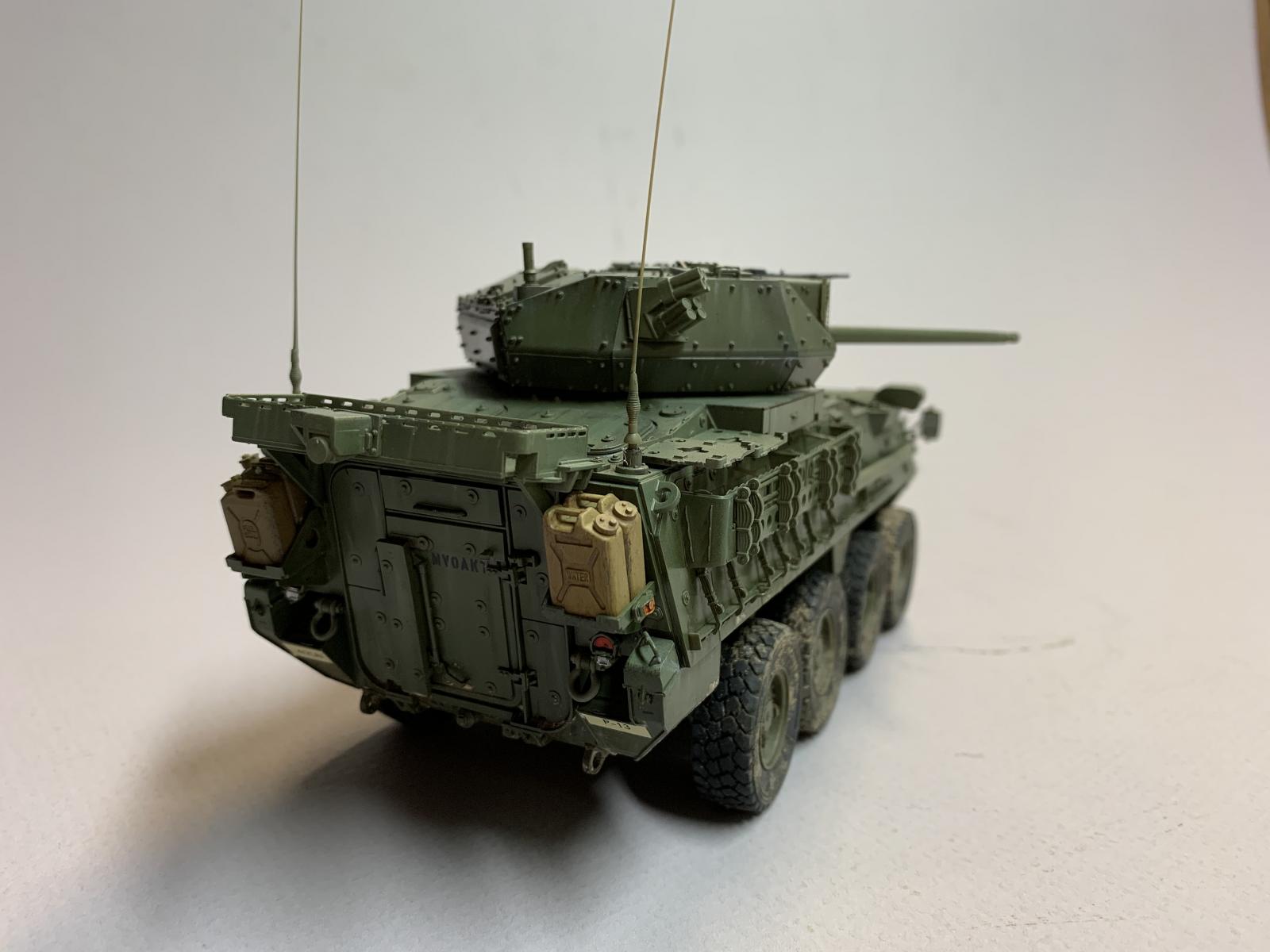
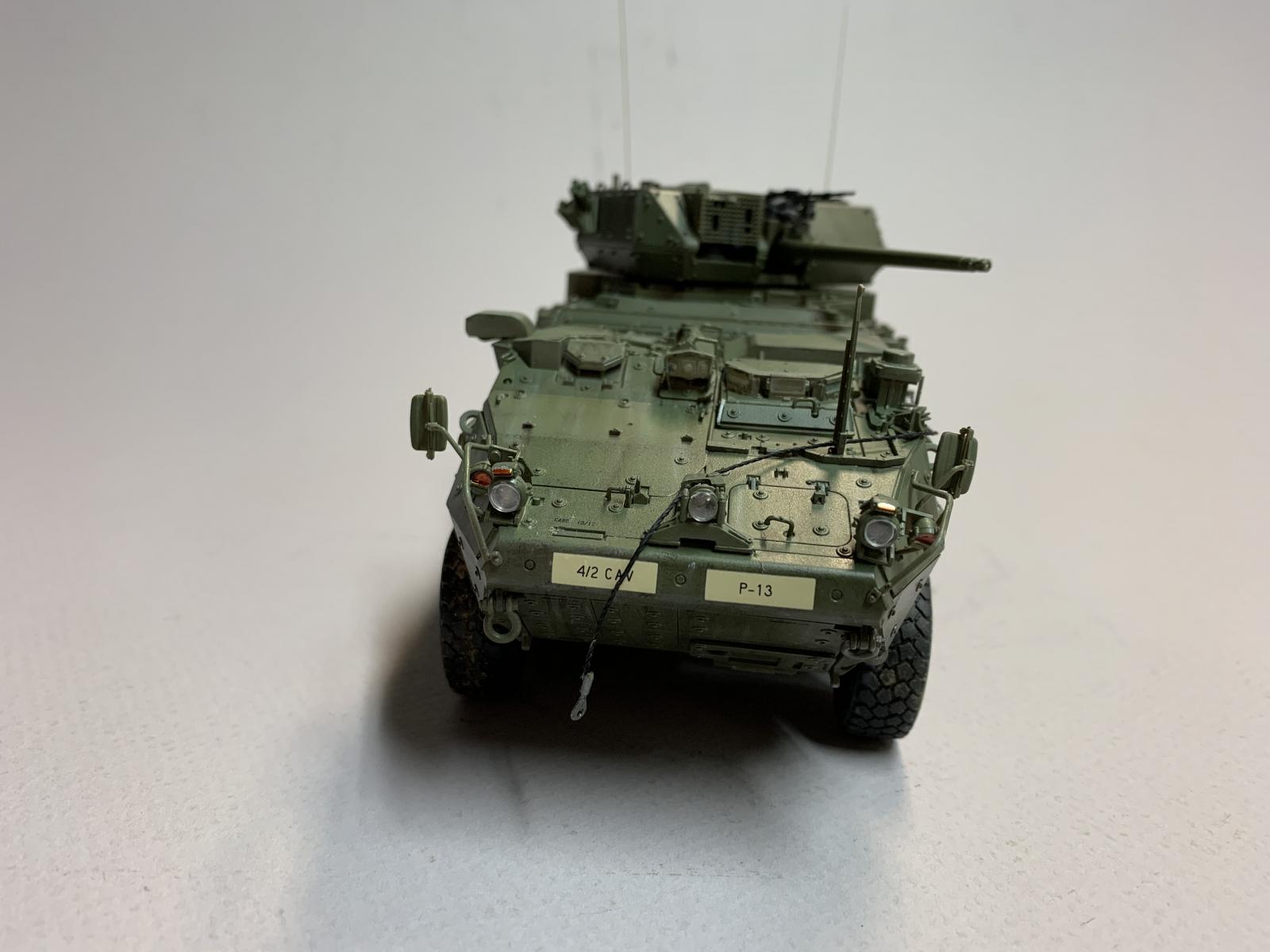
A cable and pulley system are also located on the front hull top. I held off installing the cable until the painting was complete. The short length of thread noted above was the cable. The thread was threaded through the three pulleys and fitted into the pulley drive. The thread was held in place with white glue.
Mirrors and side guards are very delicate. I mounted the guards prior to painted, but held off on the installation of the mirrors until all the painting and decals were completed. The mirror faces were made up from metal foil cut to size and held in place with Future. I used canopy glue "sludge" to fit the mirrors to the mounting brackets.
Turret
The first step is the assembly of the M2 machine gun mount and sights. Several small parts are involved in this subassembly, but they all fit together. The main armament gun barrel halves will take some care to keep the parts aligned to maintain the round barrel section throughout its length, limiting the amount of cleanup to eliminate he join line. Like the upper hull there are several individual armour plates to fit in place on the turret sides. And once again everything fit right in place.
Photoetched Parts
Three, fine mesh screens are provided for the top panel grills over the engine compartment. A spot of white glue was applied to the corners of each grill and when the mesh was properly aligned super glue was applied around the edges. The remainder of the parts on the fret were not required.
Painting
I started the painting with the tires. First I washed the vinyl tires with warm water and Dawn detergent, rinsing with clear water and allowing them to dry over night. The deep tread may hold moisture and must be completely dry before paint is applied. I put down a base of Tamiya Rubber Black XF-85, then high-lighted the sidewalls with Panzer Aces Dark Rubber. Everything was sealed with Model Master Clear Flat Acryl.
The instructions include several paint manufacturers with specific colors to be used. I elected to try the Vallejo color recommended (71093 NATO Green but noted as "Field Green" in the instructions).
The vehicle was first primed with Tamiya grey primer decanted from the spray can and thinned with Mr Color self-leveling thinner. After a 48 hour cure time I applied Vallejo Model Air 71.093 NATO green thinned with Vallejo thinner. This my first time using this paint with an air brush, but the experience went well. With the many nooks and crannies and semi-hidden places it took 3-4 sessions to get complete coverage of the exterior surfaces. The application of the light grey primer was a boost to identifying all the hidden places. The model was set aside for 48 hours to alow the paint to cure.
Decals
An application of clear gloss was applied to the entire model to facilitate the placement of the few decals and a pin wash. Again a cure time of 48 hours was allowed. Markings for six vehicles are included, with about 20 decals used for each vehicle. Each decal was soaked for less than a minute, and the decal slid off the backing quite easily. MicroSet was used for placement and each decal was pressed into place with a Q-tip. Each decal was located on a flat surface so there was issue with raised details. Once completed a clear flat finish was applied.
Bringing it all Together
The wheel hubs and tires were fitted together with any difficulty and no glue was required to hold the tires in place. When gluing the wheel hubs to the axels it should be noted the connectors are shaped and must be properly alligned. A drop of solvent was placed in the wheel hub recess and the hub was fitted to the axel. Once all eight wheels and tires were in place I clamped the assembly to make certain everything was aligned. This was set aside to harden over night. Once cured the wheels were all in alignment and all tires rested on the table top flat surface.
The interiors of the headlights and tail lights were first given a touch of Model master silver paint, and when that dried Tamiya clear red or orange was applied were approriate. Headlight lenses were fitted and Future was used to hold in place.
The turret was set on the hull after the decals were applied and the flat finish sprayed on.
Weather or Not??
For those modelers who enjoy weathering their military vehicles this model offers a great opportunity for that effort. Plan to spend a better portion of your life applying a pin wash to the many bolts, hinges, recessed panels lines and other features. I did apply a pin wash and that resulted in a subtle shading around the surface details. Those skilled in dry brushing will also enjoy that phase.
Conclusion
Although the instructions appear to be quite complicated careful study and dry fitting of the many parts during each step will assure correct assembly in the end. Some of the placement drawings are a bit vague and the part orientation is not quite clear, but with on-line images of the real vehicle the information should be clarified. I found no significan fit problems with the parts. Many parts are quite small and delicate, so care is required when removing them from the sprue. I used the Precision Sprue/Wire Round Cutter 02 from UMM-USA as recently reviewed here to remove many of the parts from the sprues. It worked well when removing the smallest of parts in this kit. I thought this kit was well engineered and the fit was quite good. The end result is a very big vehicle.
The use of vinyl for certain parts in my opinion is highly questionable. I found these parts not to be user friendly, and none were used in this build.
I wish to thank AVF Club and Hobbyfan and IPMS USA for the opportunity to build and review this kit. I have wanted to build a Stryker for quite some time, and this was worth the wait. I am quite pleased with the end result. This kit is recommended for the modern armour builder.

Comments
Very Useful Review
I'm making this kit now. I was hoping to learn about the stainless steel sleeves for the suspension. Are they glued as well? Only the plastic part that fits through? Your warning about the headlights and Q24 is well taken. Also, I'm thinking of priming and painting the lower hull at the end of step 7. Any comments / warnings?
Dragoon Weapons
There's no M2 50cal on the Dragoon. The Weapons Station has an XM813 30mm Chain Gun, a variation on the Mk 44 Bushmaster along with a coaxial M240C 7.62mm weapon.
Add new comment
This site is protected by reCAPTCHA and the Google Privacy Policy and Terms of Service apply.
Similar Reviews