
8 Inch Howitzer M1 WWII
Background
The 8-inch Gun M1 was a 203 mm towed heavy gun developed in the United States and was also used in small numbers by the British Army. Serious development began in June 1940 of an 8-inch (203 mm) gun that would have the longest range of any US Army field artillery weapon in World War II. The gun used the same projectile as the 8-inch coastal gun and the US Navy's 8-inch cruiser gun. The M1 consists of equilibrator assemblies, elevating and traversing mechanisms, two single-wheel, single-axle heavy limber, and a two-axle bogie with eight tires and two trails. After 1962 it was designated the M115 Howitzer.
AFV Club Kit
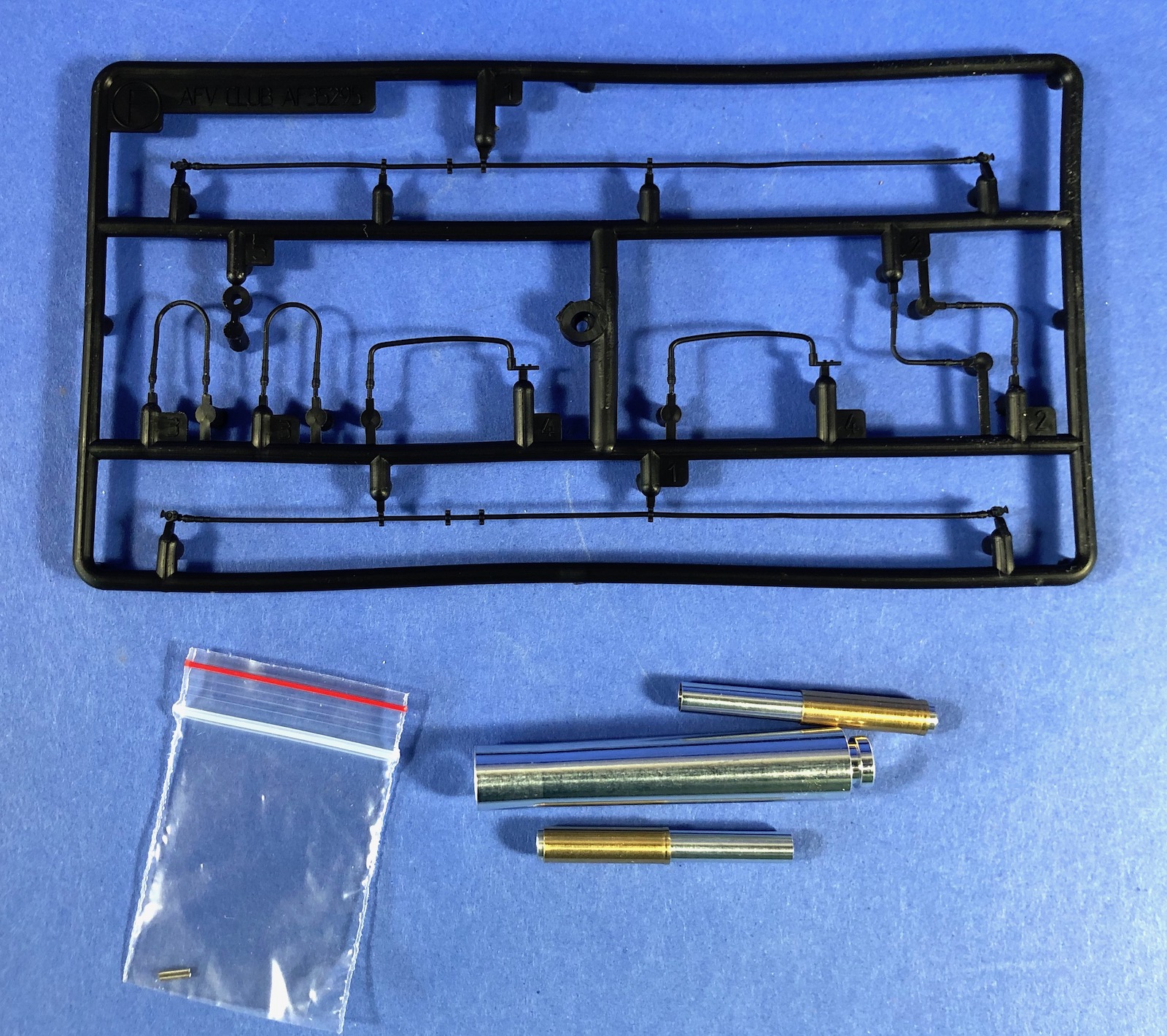
Originally issued in 1997 & reissued in 2000 as the post-1962 M115 Howitzer, this kit release has been modified to the original WWII M1 version with new parts. The new parts include:
- Aluminum rod and brass sleeves for the equilibrator assemblies
- Vinyl brake lines
- Heavy carriage limber M2
- Injection gun sight
- Injection gun bolt
- Aluminum gun barrel (with rifled end)
- M2 Heavy limber
The kit includes parts molded in a fairly soft olive drab colored plastic and have good detail. There are mold seams on most of the parts and some have minor flash (including the bogie sprue B). There are a few parts with misaligned molds. The sprue connections are fairly large, so care is necessary when cleaning them up. Several figures are shown on the box art but are not included with the kit.
Assembly
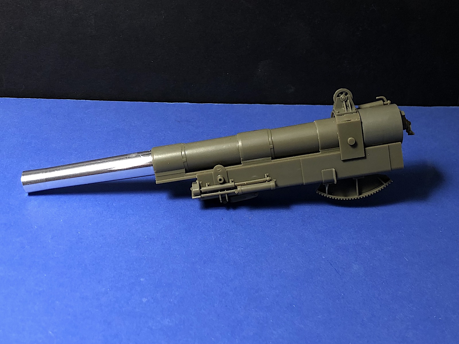
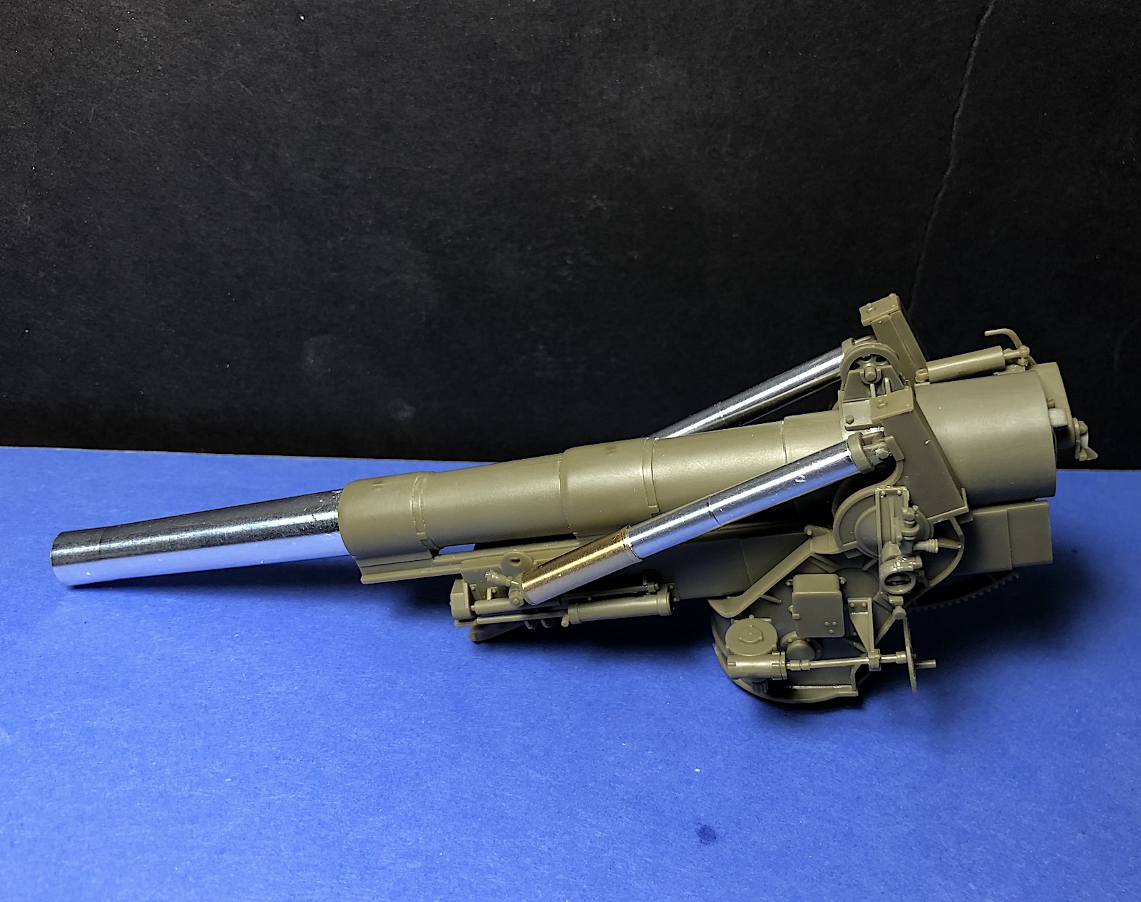
The first two steps assemble the barrel, which includes an aluminum upper section and lower plastic section. There will be a seam on the plastic parts that needs to be cleaned up. The threads on the breach are installed half on the breech and half on the block. The different sections of threads will need to be smashed together to allow the breechblock to close. I am modeling the gun in transport with a closed breech, so I left off the E48 threads on the breechblock section.
Steps 3 and 4 assemble the recoil assembly and install the barrel. The travel lock, part B33, is installed between halves of the recoil assembly. It can be left unglued to position later depending on whether the gun will be in the firing or traveling configuration.
Steps 5 and 6 assemble the upper carriage for the gun. There are several very small parts in these steps. Fit is generally good although there are some parts without locating pins that need to be placed. The elevating gear C46 is not glued in place which will allow the gun to elevate when installed. Step 6 installs the barrel and recoil assembly into the upper carriage, with a somewhat loose fit. The carriage arms are too far apart to hold the barrel in place if unglued. The small detail a shows assembly of the tail spades, of which 2 are required.
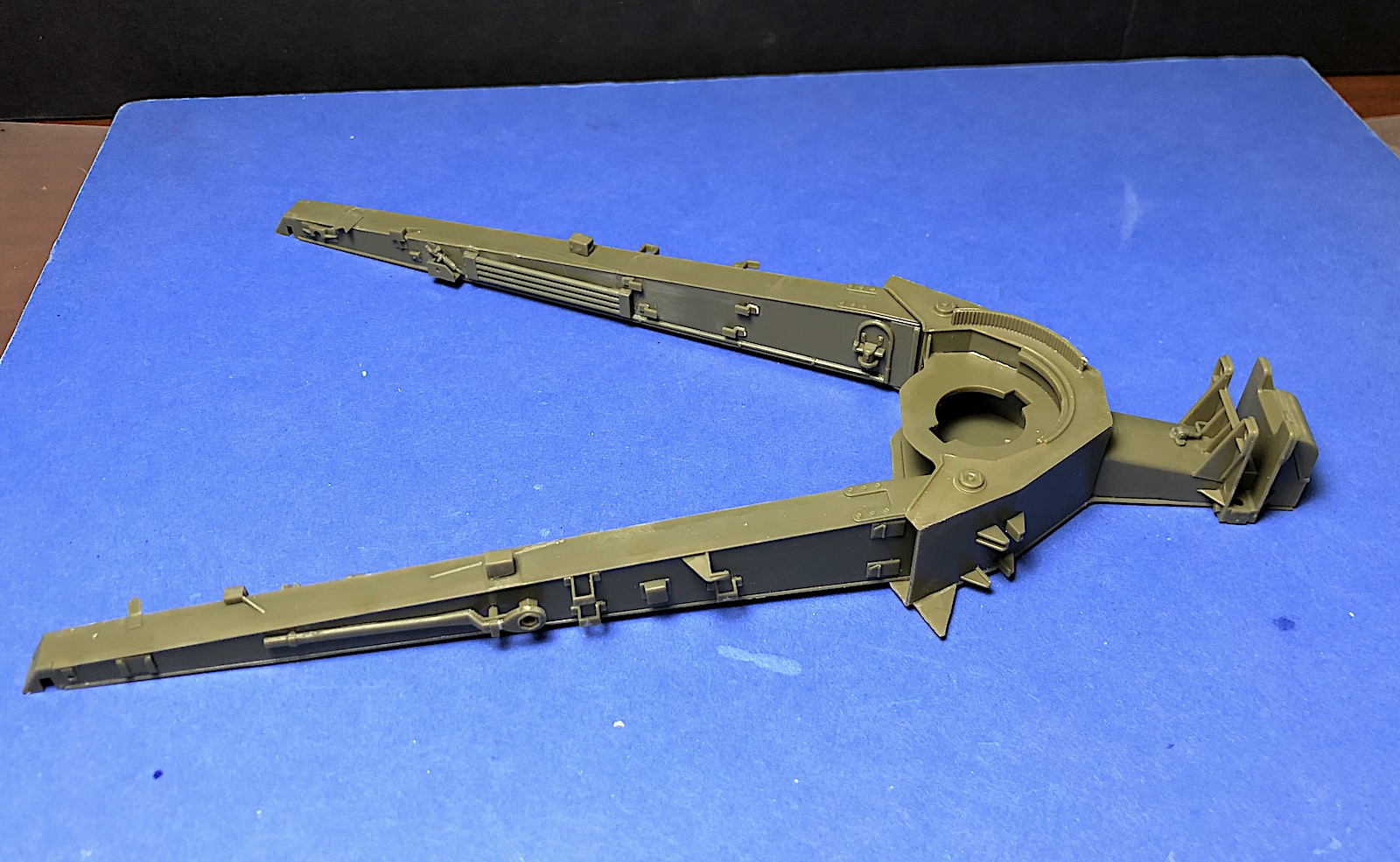
Step 7 builds up the trails for the gun, but is fairly confusing. The box on the middle of page 6 shows detail to be removed and parts added but is not clear that part A12 is actually reversed. Holes are shown to be drilled in the trails for brake cables in step number 16, but it may be easier to do it now.
The equilibrators are built and assembled in step 8 with aluminum cylinders and brass sleeves that fit very nicely. Avoid getting glue on the plastic equilibrator ends when installing to the gun to allow the barrel to be raised and lowered.
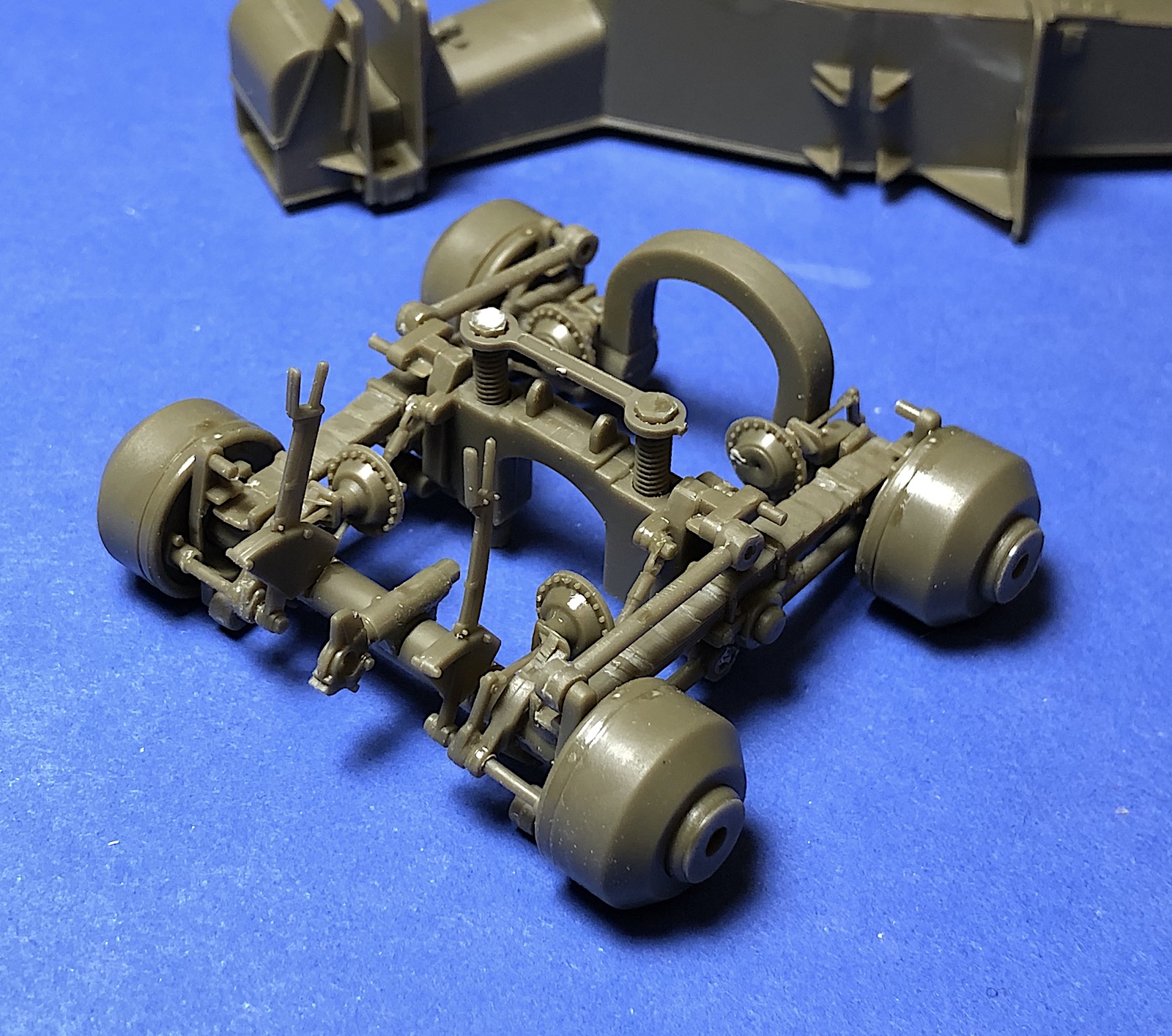
The carriage bogey is assembled in a complicated step 10. The axles are shown not to be glued to parts B31, but they are subsequently locked in place by parts B34 & 35. Note that the front axle B37 has an in and out orientation so make sure to install with the slots opening to the outside. The struts B34 in B35 or very thin and delicate.
Step 11 is a very challenging step that installs the brake levers and air receivers. Instructions show a 0.5mm hole to be drilled in parts B4 but I found 0.6mm holes were a better fit for the subsequent brake lines. It would be good to install the brake lines into parts B4 in this step as they are not very accessible later on.
The inner wheel drums and struts are installed in step 12. The parts B29 are not glued inside the wheel to allow the wheels to rotate. The step also shows the struts not to be glued to the inner wheel backing plate, but the other ends are glued so there won’t be much movement. Step 13 shows installation of the elevating jacks and front bogey to the trails. The end of the brake hoses should be connected to the brake air drums prior to this step.
The bogey wheels and tires are assembled in step 15. The rubber tires have a very nice tread and sidewall detail. The tires can be installed after the wheels and hub are glued together to facilitate painting.
The top carriage is installed to the bottom carriage and step 16. I had trouble getting them fit together and head to enlarge the opening in the bottom carriage and reduce the size of the tabs to get them to fit. The gun carriage will rotate but with some difficulty.
Step 17 is optional to show the gun in firing position with installation of the front and trail spades. Part C20 fixes the elevation angle of the gun. Step 20 shows configuration of the gun in a towed configuration option with the spades stored.
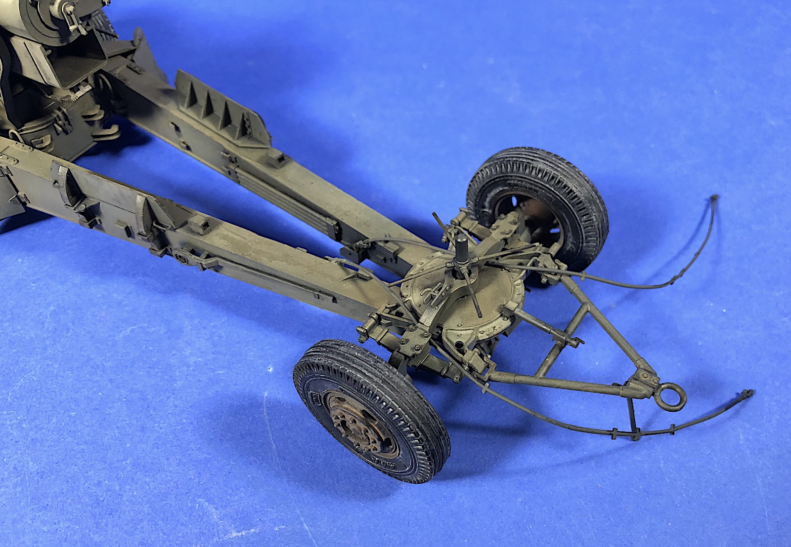
The front limber is assembled in steps 18 and 19 in a fairly complex series of parts. The leaf springs parts D16 and D17 have a different anchor configuration than shown in the instructions. One end of the spring is held by a small metal rod. There are two options for the limber elevating screw, D2 or D4 depending whether the gun is in towed or firing configuration. The limber assembly ends up being a fairly delicate assembly considering the large mass of the gun itself.
The last assembly step 20 configures the gun for a towed configuration by storing the trail spades and adding a reflector to the gun barrel. There are several options for the barrel tools.
Pages 14 and 15 are color profiles of the gun in an overall olive drab color scheme, and the last page shows images of the sprues and parts.
I spent about 15 hours on assembly, plus another 5 or 6 hours on finishing of the kit.
Summary
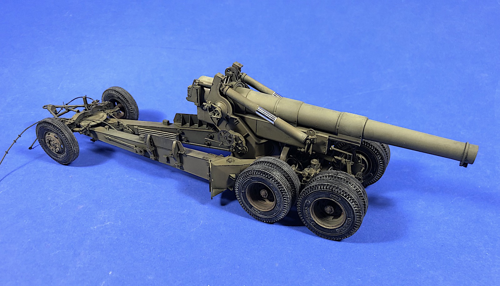
AFV Club’s kit builds into an impressive model of the M1 Howitzer. The part fit is good and the detail on the gun is very good. There are some challenging steps due to small parts and the complicated structure of the gun, so the kit would not be easy for beginning model builders. The new parts with this version add nice detail to the kit. The kit parts are still in good shape despite the age of the model.
Thanks to AFV Club for producing this nice model and providing a review sample to IPMS.


Comments
Add new comment
This site is protected by reCAPTCHA and the Google Privacy Policy and Terms of Service apply.
Similar Reviews