
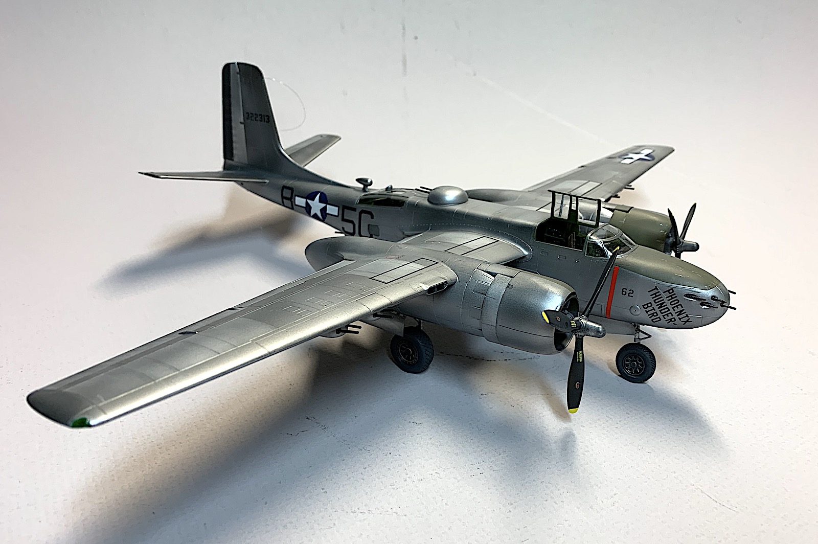
A-26B-15 Invader
Brief History (from Wikipedia)
The Douglas A-26 Invader (designated B-26 between 1948 and 1965) is an American twin-engined light bomber and ground attack aircraft. Built by Douglas Aircaft Company during World War II, the Invader also saw service during several major Cold War conflicts. A limited number of highly modified United Sates Air Force aircraft served in Southeast Aisa until 1969. It was a fast aircraft capable of carrying a large bomb load. A range of guns could be fitted to produce a formidable ground-attack aircraft.
A re-designation of the type from A-26 to B-26 led to confusion with the Martin B-26 Marauder which first flew in November 1940, some 20 months before the Douglas design's maiden flight. Although both types were powered by the widely used Pratt & Whitney R-2800 Double Wasp eighteen-cylinder, double-row radial engine, they were completely different and separate designs – the Martin bomber originated in 1939, with more than twice as many Marauders (nearly 5,300) produced in comparison to the Douglas design.
The A-26B variant is an attack bomber with solid nose carrying six or eight 0.50 in (12.7 mm) machine guns. Production totals: 1,355 A-26Bs were built and delivered, 205 at Tulsa, Oklahoma (A-26B-5-DT to A-26B-25-DT) plus 1,150 at Long Beach, California (A-26B-1-DL to A-26B-66-DL). About 24 more airframes were built at Long Beach but not delivered to USAAF, some of those later sold to other civil and military customers. A-26B was re-designated B-26B with USAF in 1948.
The A-26 Invader saw service during World War II in Europe, and the Pacific, later in Korea and Viet Nam. Foreign service included France, Brazil, Chile, Biafra, China, Columbia, Congolese Republic, Cuba, Cuban Rebel Air Force, Dominican Republic, Guatemala, Indonesia, Laos, Honduras, Mexico, Nicaragua, Peru, Portugal, The Royal Air Force, Saudi Arabia, Turkey and Viet Nam. There were several civilian Invaders used in races, fire bombers, and military applications testing firms.
Instructions
The instructions are provided in a 24-page, glossy paper book format. The cover page offers a brief description of the aircraft and includes a paint and color schedule based on Revell and Tamiya acrylic paints. The bottom of the page includes an instruction legend. The next three pages address the sprue layouts with parts identified as not to be used.
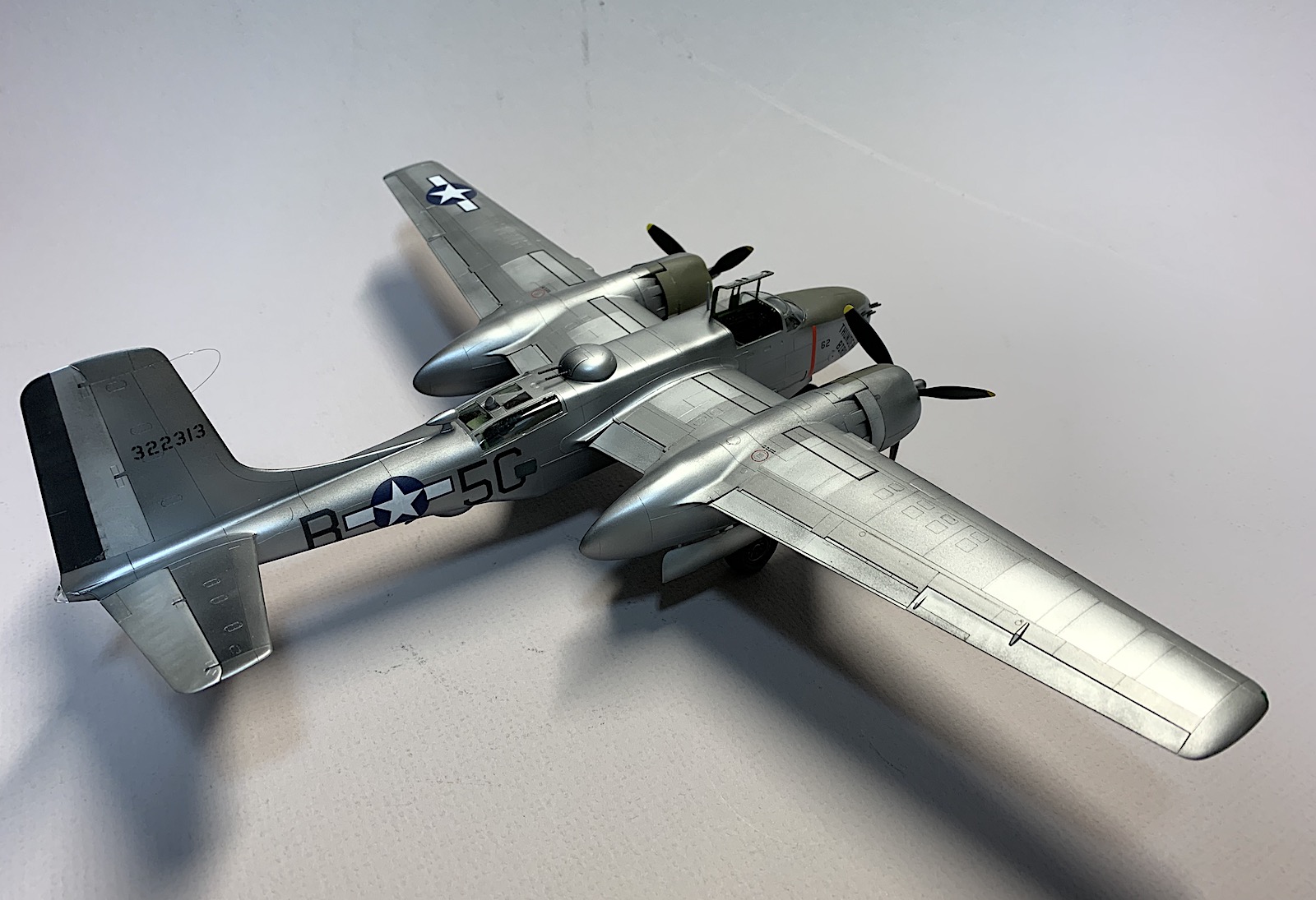
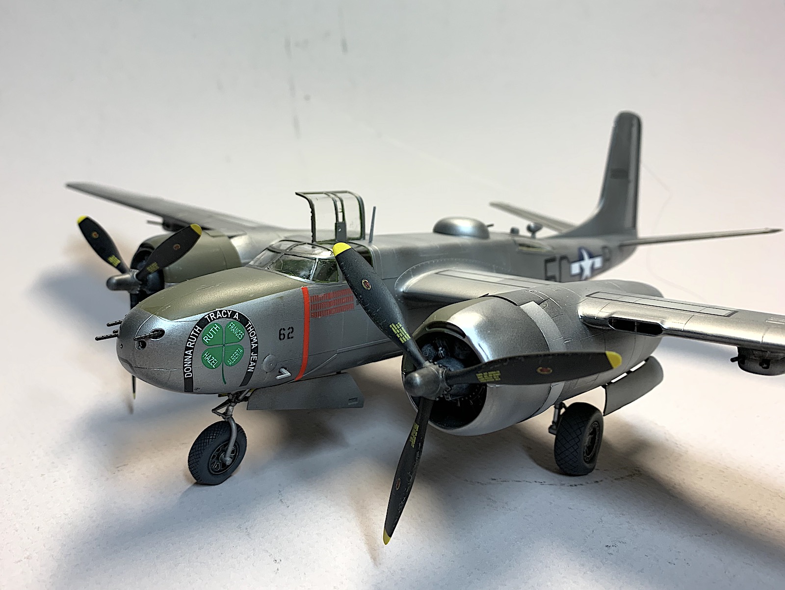
Pages 5 through 22 detail the assembly of the model with 96 individual steps shown. Each step is presented as an isometric or exploded view with the parts numbered and paint colors identified. The last two pages show the decal placements for the three aircraft that can be built from this kit. All are natural metal aircraft.
The Kit Parts
There are ten sprues included: All ten are bagged in a common clear plastic bag, except the clear parts are bagged separately within the main bag. Kit parts are molded in a medium grey plastic. There were some loose parts in the bag that had separated from the various sprues.
Clear Parts
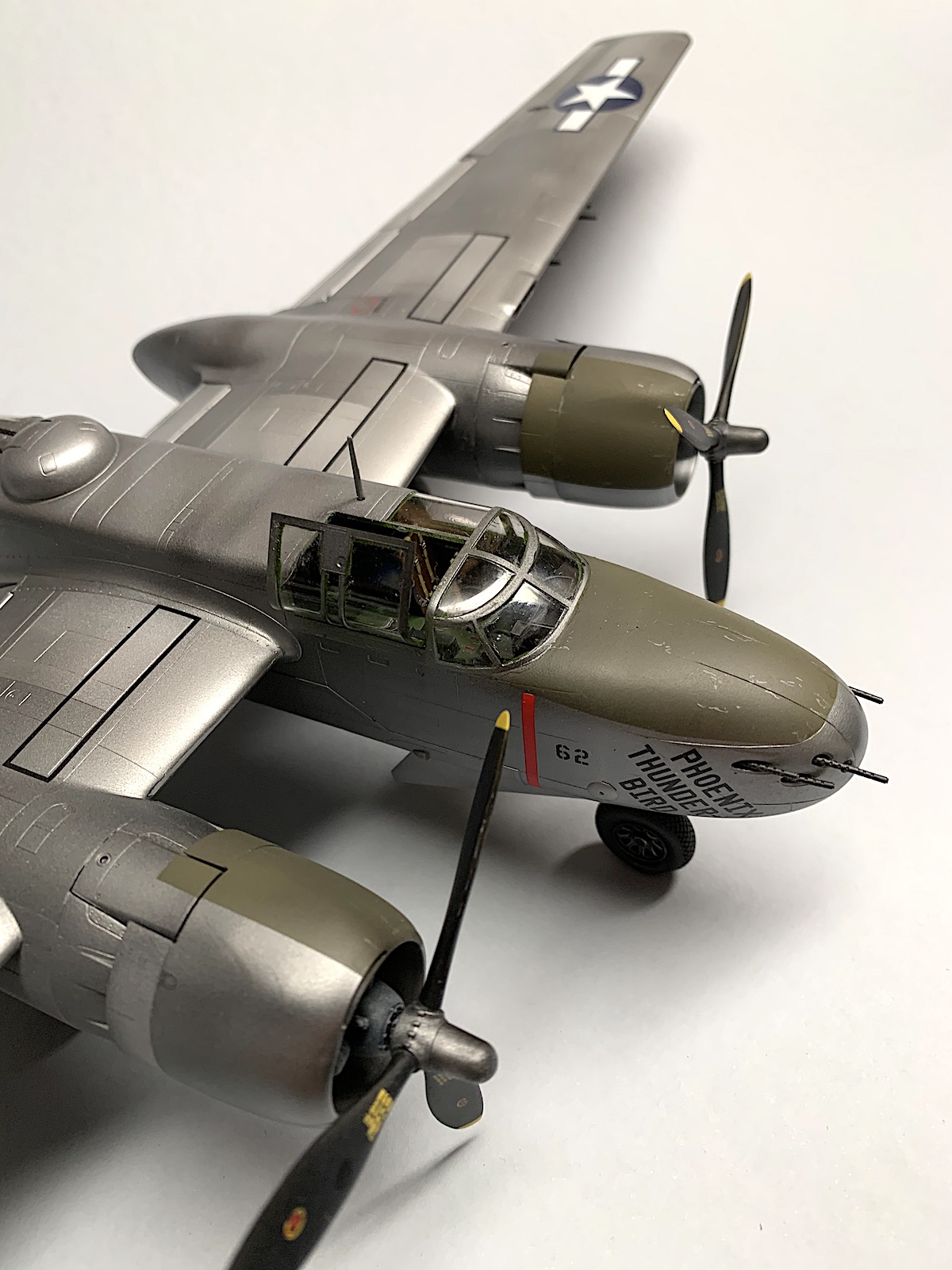
Two canopies are included with one not to be used per the instructions, while the remaining canopy has an open section for viewing into the cockpit area. The smallest parts provided are for the underwing landing lights, extreme rear fuselage micro windows and wingtip navigation lights.
Construction
Cockpit
Several small sub-assemblies make up the cockpit construction. These sub-assemblies were painted and decaled before being brought together. As noted in an earlier review of the ICM Invader the instrument panel dial decals are individual decals. I cut them into strips of three to four decals and applied them individually. Needle nose tweezers, a steady hand, and a sharp eye will help in the placement.
Fuselage
The cockpit and bomb bay side walls are molded as part of the fuselage sides and are nicely detailed. The floor of the cockpit includes the rear bulkhead and wing spars for the later mounting of the wings. There is a second bulkhead with wing spars a bit further back, plus two additional bulkheads that define the rear gunner's position. This proved to be a solid foundation for the fuselage assembly.
In steps 12 and 15 the bomb racks are to be fixed to the side walls of the bomb bay. The instructions show mounting stubs to receive the two bomb racks per side, but the kit sides do not include the stubs. It was unclear as to how to mount the rack, and therefore I left them off for the time being.
The cockpit and rear gunner's position were painted interior green, while the bomb bay was painted zinc chromate. I later decided to close the bomb bay to preserve the lines of the aircraft.
Wings
Since this aircraft was fitted with two twin machine gun pods per wing, holes must be drilled in the bottom half of the wing before the wings are assembled. There are several hole locations molded into the inner surface of the wing bottoms, however the instructions are quite clear one which holes must be opened. Wing flaps and ailerons are all individual parts and may be posed if desired.
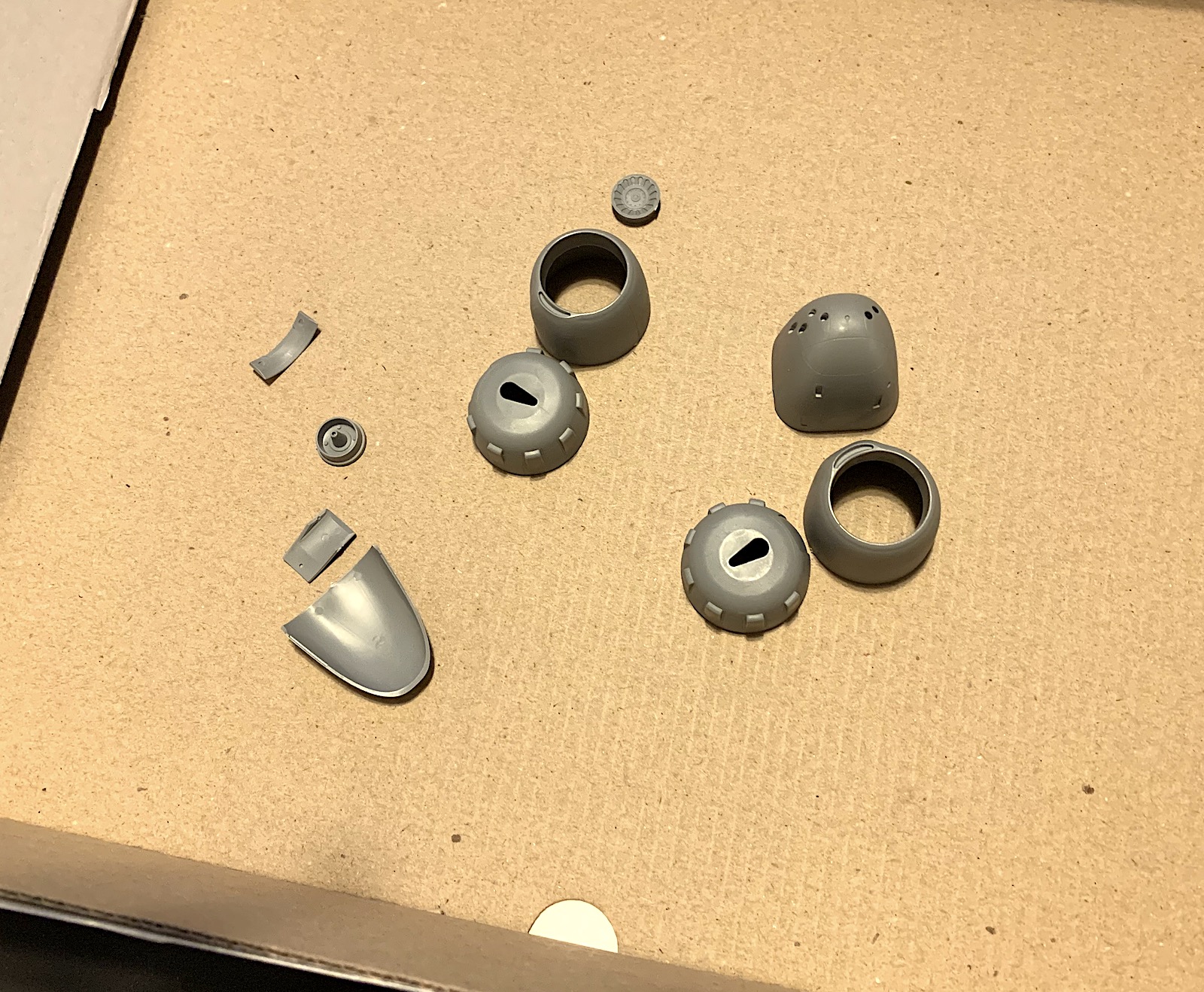
Engines
The engine nacelles are comprised of two halves, two interior bulkheads and two doors. ICM has done a fine job of designing parts for the doors that are securely fixed to the nacelles. Again, I painted the interiors before the two nacelles halves were glued together. Care is required when fixing the bulkheads in place so that the nacelle halves fit and close together properly.
Each engine is made up from 16 parts plus nine exhausts. A single plastic jig (part E34) is included to assist in the placement of the individual exhaust stubs and appears in step 80. The jig is to be dry-fitted and is not a permanent part of the model.
Propellers
Each propeller is attached to the sprue by a single connector. This was easily cut and cleaned up. Other than that the propellers look perfect.
Weapons
The underwing gun pods are each made up from four parts and proved to be a bit fiddly to assemble.
The four bombs are assembled from two halves and a tail-mounted fuse with propeller. These were quickly assembled. The wing mount bombs were not used as I planned to use the underwing gun pods in this build.
Landing Gear
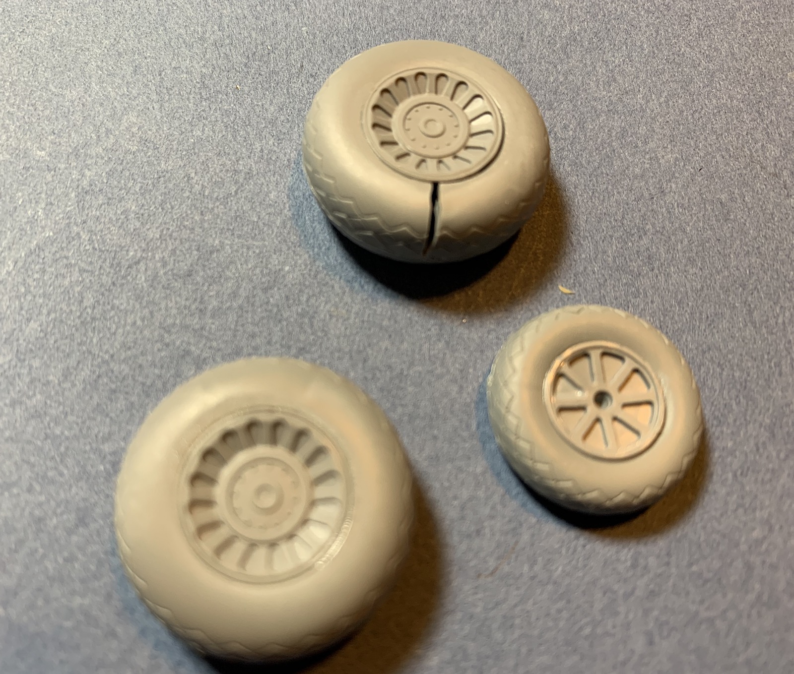
Nothing complicated here, and assembly went well. The only concern was the small mounting surface of the axel-to-wheel hub. I addressed that with a minor modification that added a short length of brass rod inserted into the wheels.
Each wheel and tire assembly is made from two tire halves and two hubs. With the first wheel I may have inverted the assembled tire because when I fitted the exterior half of the hub to the tire the fit was too tight. I pressed the hub into place and applied the solvent. Within a few seconds the sidewall of the tire cracked perpendicular to the hub. Since the gear side of the hub was already fitted and glued, the assembly appeared to be unsalvageable. I assembled the other main wheel but was careful to make certain the hubs fit in place without being forced. They did and were then glued in place. No splitting or cracking with the second tire/wheel assembly. Lesson learned
I had a set of True Details resin wheels and used those in lieu of the kit parts. Ruining the kit wheels falls on me and not ICM. Their parts would work perfectly if only I had been more observant.
Painting
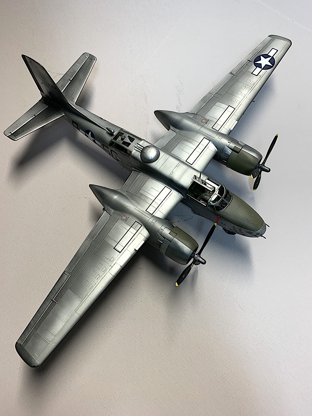
The model was primed with Alclad black primer and allowed to cure for 48 hours. The natural metal finish was applied with various shades of Alclad and Model Master metallic paints. The anti-glare panels were painted with Tamiya acrylics.
The propellers were first painted with white primer, yellow tip painted and masked, and finally the blades were painted flat black. The hubs were dry-brushed with silver Rub-n-Buff.
The wheels were painted flat black, hubs dry-brushed with silver Rub-n-Buff, and the tire hand-painted with Panzer Aces Dark Rubber.
Landing gear was painted with Alclad black primer and over-sprayed with Alclad Dull Aluminum. Oleos were painted chrome.
Decals
The decals are provided on a small sheet and include markings for three natural finish aircraft. Each decal was cut out separately and dipped in warm water for a few seconds. After a minute the markings were slid of the backer sheet and into place on the model. I used Microset to float the decals into location and after removing the water from below the markings used Microsol to have the decals conform to the surface.
These are really nice decals that floated on the model's surface and had minimal carrier film that truly disappeared as the decals dried. The kit's recessed panel lines are very, very fine engravings and created a bit of a challenge for the decals to recess into. I used a sharp hobby knife to score the decals where they crossed a panel line.
Once the decals had dried overnight the model was given a coat of Model Master Clear satin finish to eliminate the glossy decal sheen.
Bringing it all Together
The completed engines were fitted to the nacelle and glued in place. The engine cowlings are a really tight fit and some care is required to get them in place. The left engine cowling did not close to the rear nacelle entirely, and therefore I stopped before disaster struck. No glue was required to hold the cowlings in place.
The landing gear were fitted in place and allowed to cure overnight before the wheels were glued to the axles and the flat surfaces matched to a flat surface. The nose gear is a bit of a delicate assembly so care is required during placement. The propellers were mated to the engines again without glue.
I used smoke-colored invisible thread for the antenna.
Conclusion
The kit parts are crisply molded, with no flash on this example, and had very few exposed ejector pin marks. The plastic is a bit soft and this probably helped in the removal of attachment spurs from the various parts. I used Tamiya thin cement in this build and the plastic responded well to its use. This is a very fine kit and is highly recommended. Happy to see that ICM is offering several versions of this aircraft.
I wish to thank ICM Holding and IPMS USA for the opportunity to build and review this kit.
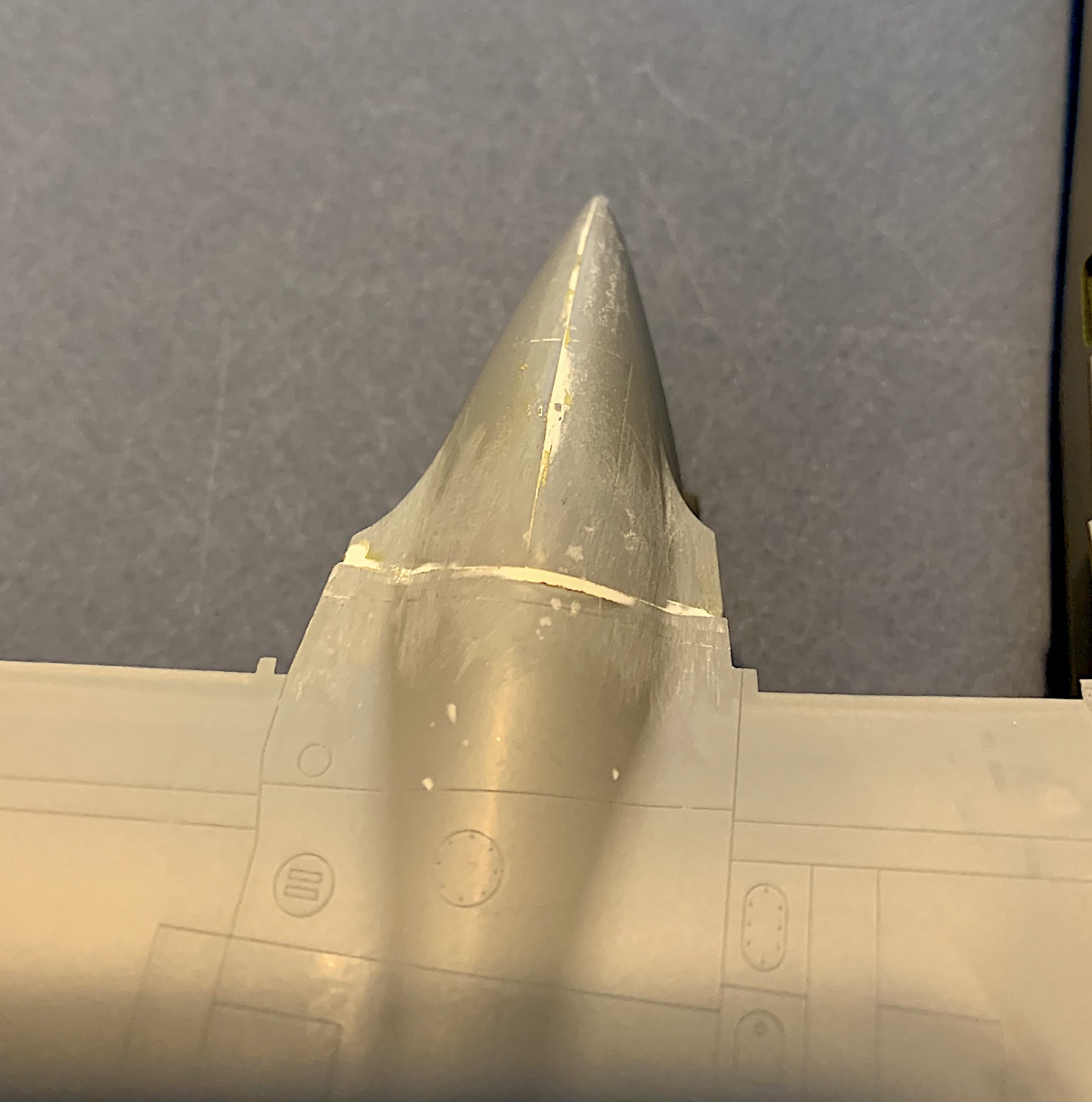
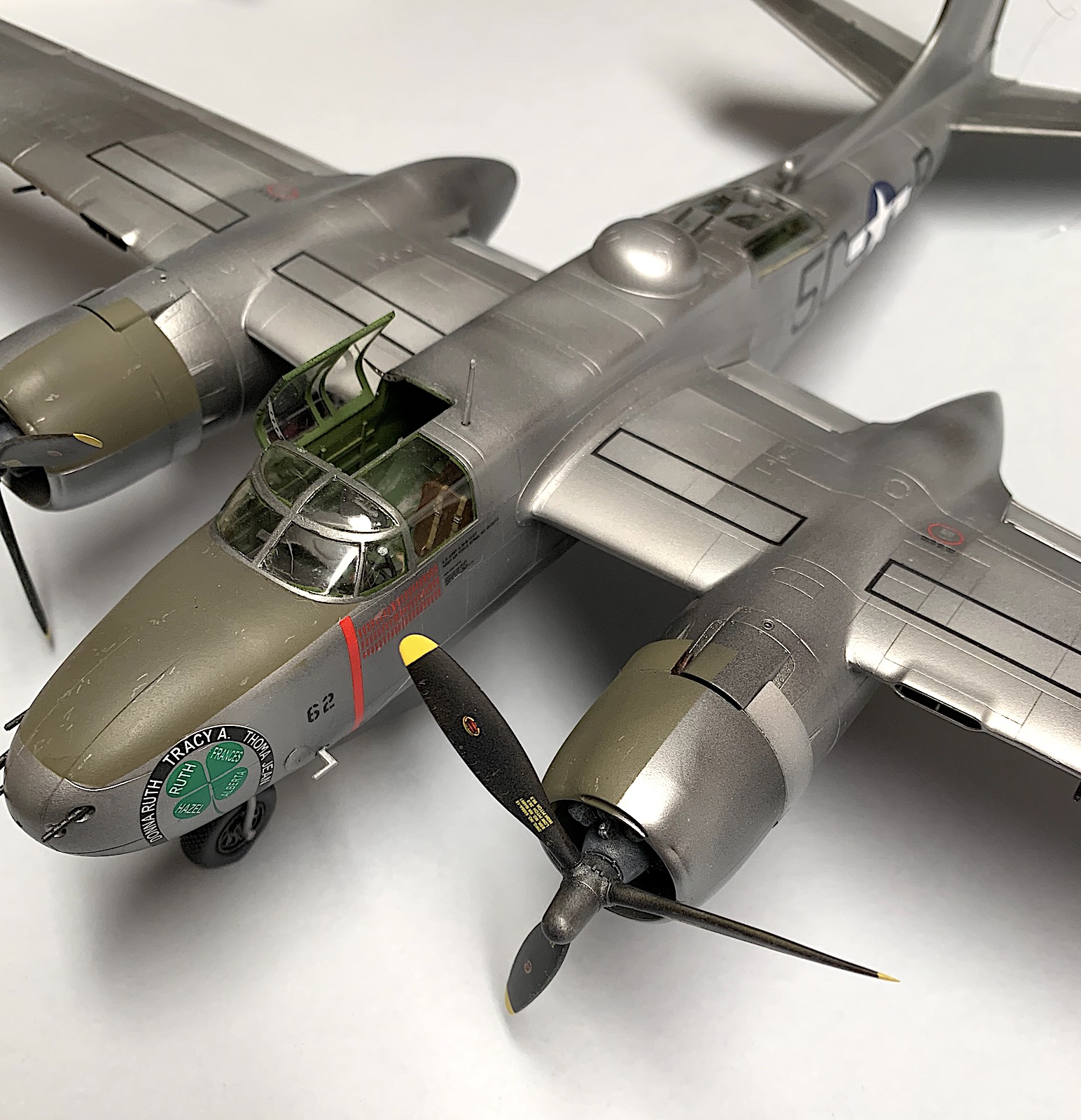
ICM A-26B-15 Invader Canopy Installation Correction
This Modeler's Construction Assembly Error
Our local club has suspended our monthly group meetings for the duration of the current Covid-19 pandemic concerns. As a group we decided to stay in touch via the Internet and keep each other informed of our current modeling projects, help each other with possible modeling issues and concerns, as well as check on our individual well-being. I decided to post images of my recently completed ICM A-26B-15 Invader as some members are not IMPS/USA members.
One of the younger members sent me a private email noting that I had installed the right-side open canopy section incorrectly. This comment was done in a very polite, respectful and dignified manner, which I truly appreciate. He was right!
What Happened?
The first thing I did was check the instructions. ICM does not show the canopy section in an open configuration. I had neglected to check my references to verify how the open section on this particular should be mounted. After reviewing several sources, I found there were two variants: the early version with the front hinge, and the later which would become the more popular lower side hinge.
I picked the variant that did not exist. My mistake entirely.
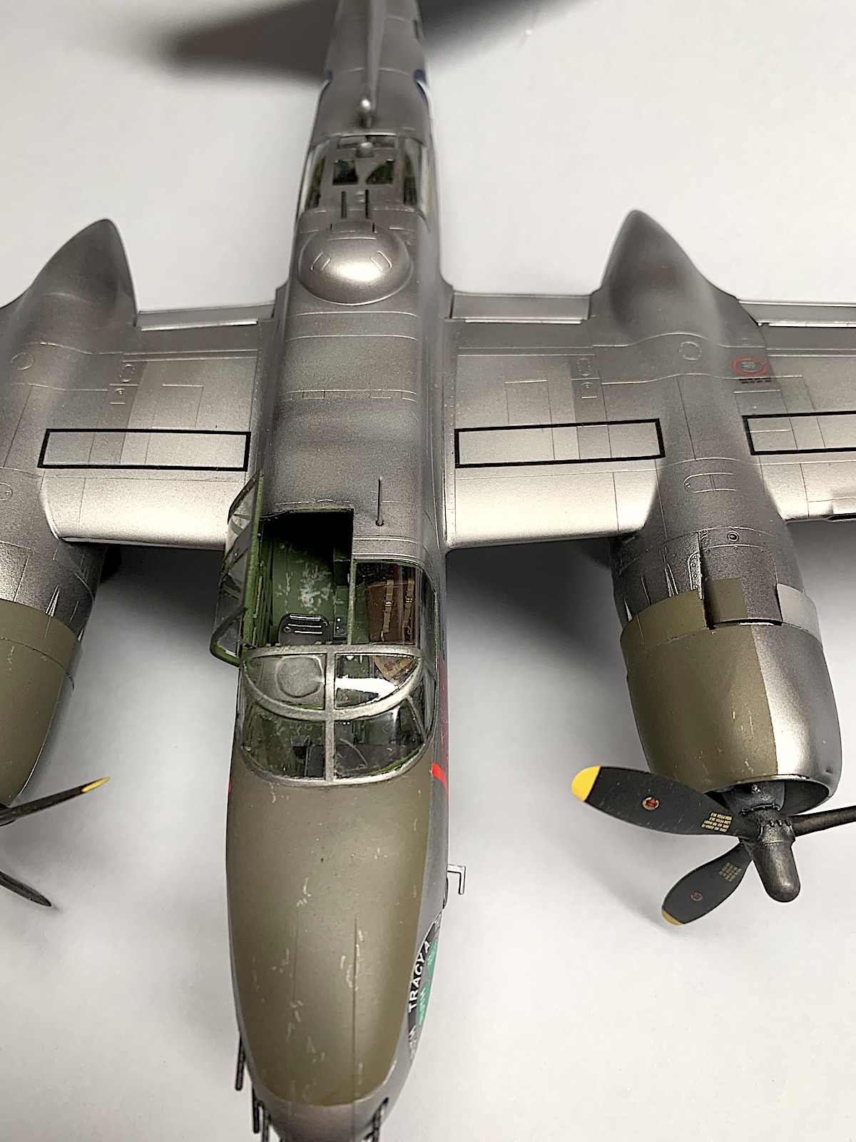
Fortunately I had mounted the open canopy section with Formula 560 and was able to remove the clear part without much difficulty. I used the same adhesive to fix the canopy as the correct lower hinge mounting.
Conclusion
I stand by my earlier recommendation for this fine kit. The blame for the canopy mistake is completely mine and in no way should diminish the ICM kit. The references are out there. I just needed to pay attention.
As I had stated previously in my review this is a very fine kit and is highly recommended. I have included a few images of the corrected model and apologize for any confusion I may have caused.
I wish to thank my club friend for his constructive input to correct my mistake. Much appreciated.


Comments
Thanks
Thanks for the comment. It will be passed along. We do not strive (contrary to popular opinion) for accuracy. We are pushing our emphasis on the buiuld and people behind it.
Dave
Add new comment
This site is protected by reCAPTCHA and the Google Privacy Policy and Terms of Service apply.
Similar Reviews