F6F-5 Hellcat, Part 2

With the major fuselage and wing assemblies completed in Part 1, I continued on with Part 2 of the 1/24 Airfix Hellcat F6F-5 build.
The tail planes, elevators, rudder and ailerons with their respective, movable, trim tabs were glued together with minimal problems. Make sure the elevator hinges are inserted the correct way… I got it wrong…twice!!! Luckily, the glue was still wet so I could pry the elevators open and correct my mistake….twice!!!! The instructions clearly show the correct way to install these.
I also assembled the inboard and outboard flap sections, but, left them off the wings until later. The left outboard wing flap top half was badly warped (see pictures). I used a hair dryer to heat and bend it back to shape with limited success. I ended up gluing the top and bottom together and clamping the flap to a flat wooden dowel, which did the trick!
The center wing assembly and fuselage were brought together resulting in a pretty good fit. I ran a bead of putty along the wing roots to eliminate a very small gap. The tail planes followed and fit securely. Putty filled thin gaps in the seam lines.
The next major project was the Pratt & Whitney R-2800 Double Wasp engine. It is very detailed and everything fit quite well. The only item I could see missing in the kit was the Pratt & Whitney logo. I photocopied a logo off the internet, shrunk it down and glued it in place. The engine block (tube) contains a length wise slot that the intake manifold, the two cylinder banks and reduction housing slide over to ensure correct alignment. The fit was extremely tight.
The Airfix electric motor was inserted into its housing which was them seated tightly into the reduction gear housing. Of course, I tested the motor prior to installation. After the engine and the extensive array of intake ducts were built, the wires were fed through the carburetor air/oil cooler inlet ducting and into the rear fuselage via holes I drilled in the sides of the oil cooler screen. A momentary “push button” switch, battery box and electric wires were soldered together to complete this step. The switch and battery box are small enough to hide in the rear fuselage.
Page 41 of the instruction manual was dedicated solely to adding ignition leads to the radial engine. It suggested using 0.7mm copper wire. I found Detail Master, DM-1301, braided wire was close in diameter and looked just like the braided sheathing often used on the real ignition leads. Each pack contained two feet of braided wire and three- and three-quarter feet of lead was needed. I painted it a mix of copper and silver. Digital calipers were used to measure each length and a new Exacto blade was used to cut each lead. I worked from the shortest to the longest lead, cutting the amount of each length needed and superglued them to the ignition ring, part J25. This ring was then glued in its place and each lead was fed into its spark plug hole. Adding ignition leads to this scale of engine is really a must and the end result is fantastic. It looked quite daunting but following the instructions and a little forethought made this a fairly painless exercise.
Each cylinder had its own intake and exhaust pipe (there are a lot of them!!). All mold seams were removed, and, as the exhaust pipes were all different, I glued an end to a toothpick and numbered each one. All pipes were then painted and weathered. They all fit into their slots with minimal issues.
There are fifteen separate engine cowling panels and a choice of four open or closed cowl flaps. All these parts had between two and six ejector pin marks each. Some quite deep that needed filling and sanding.
The canopy and other “glass” parts were beautifully clear, although there was a small speck imbedded inside one pane on the sliding canopy. I used a razor saw to remove each part and carefully cleaned up the sprue attachment stubs. Extra care was needed removing the wing tip light covers as the sprue attachment was on the side. I sanded off the sprue stub and then polished the cover until it was clear again. Having the sprue stub attach to the mating surface of the light cover would have reduced the need for such careful removal and cleanup.
I masked all the clear parts with Eduard’s masking set, LX005, and prepared the aircraft for painting.
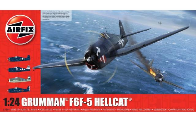
After debating whether to do the British subject, I chose to model the second US Navy F6F-5,# 32, from VF-12, that served aboard USS Randolph in 1945. The overall finish is Model Master Enamel gloss dark sea blue. The tail is painted in horizontal blue and white stripes. See the tail picture for stripe placement and measurements. I also chose to use Top Notch masks to paint the white Stars and Bars and the three sets of number 32. Model Master Enamel Classic White paint was a good match to the white stencil color. In the end, I could have just used the kit decals which, while thick, laid down nicely with Micro-Sol.
The stencil decals were all applied and adhered fine. Silvering under some stencils was taken care of with Micro-Sol? Note that a number of stencils reference two numbers depending on whether the lettering was black or white. My ailerons were white, so a black stencil was used on those. The British Navy Hellcat used the black stencils also. All other stencils were white lettering. A gloss coat sealed the decals.
There are a few good internet pictures of #32 aircraft on the carrier deck in 1945. They show it to be quite glossy and in very good condition. I decided to minimize the amount of weathering and wear and tear to some selective paint chipping around the edges of service panels and foot traffic areas. On the other hand, extensive exhaust staining was applied with pastel chalk and carefully flat coated.
Once the main airframe was done, attention returned to the front end. A bulkhead containing ductwork starting at the side intake filters and leading into the engine block was glued to the rear of the engine. This effectively hides most of the work done on the exhaust pipes feeding into the cylinders! Check the alignment of this bulkhead using the cowling panels. I didn’t get it quite right and some of the side and underside cowls don’t fit quite right. I think my issue may have been joining the engine mounts to the rear of the bulkhead.
The engine mounts slot firmly into the firewall. With the engine and airframe joined together the sheer size of this model becomes apparent!
When Phil at the IPMS sent me the RB Production seat belts, he also included a set of Scale Aircraft Conversions white metal landing gear if I wanted to use them. I have submitted a separate review for these. I ended up using the plastic kit landing gear as they were very sturdy, and I liked the detail and fit better. The main legs were in two lengthwise parts that joined above the oleo and a two-part torque link finished each leg. These were painted dark sea blue and when dry slotted firmly into the undercarriage bay along with their retraction strut. The fit and alignment of the legs were simply superb. The best I have ever seen! I applied bare metal foil to replicate the oleo.
The tires and main wheels fit perfectly, but, be aware that the diameter of the wheel is slightly different on either side, so the tire will only go on in one direction. If you have to force the tire onto the wheel, you have it the wrong way. In Part 1 of this review, I mentioned that the tires could have had better cross hatch tread detail, but after I took the time to reinstate the tread lost from sanding the seam, the tires looked quite good. There are aftermarket alternatives, but, mine are fine. They were painted Tamiya tire black and weathered with a gray wash. The wheels could be made to rotate, with a little modification, but, with the tire flat spot, I glued them on the axel.
The center line belly fuel tank, 500Lb bombs and racks were assembled and painted earlier in the build. 1000Lb bombs and rockets are also supplied as options that I did not use. All fit together nicely. With the aircraft sitting on its wheels, I attached these parts. I also glued the flaps in place. Some sanding and trimming of their mounts were needed for better fit. Some just needed paint removed, but, others needed sanding down.
I had accidentally snapped the tail antenna mount at the start of the build and left it off until later. To make it stronger, I drilled small holes in the antenna base and the tail top and inserted some brass wire before supergluing the antenna in its spot.
The massive propeller came in two parts, with a separate blade face/hub insert. Two rear hubs are offered (L46 and L47) depending on if the electric motor or the plastic prop axel is used.
The right folding wing was attached to the center wing section via a sturdy wing fold assembly. This slots firmly into the forward wing spars. Antenna wire was attached using fishing line that I painted black with a Sharpie and I called this Grumman F6F-5 done!
As large and daunting as this kit looks, it should not be too difficult for the average modeler to build. No aftermarket goodies are really needed, and, out of the box, it will produce a stunning example of one of the best fighters of World War II.
I would very much like to thank Airfix for producing such a fantastic model and the IPMS for entrusting me to build and review it.


Comments
Add new comment
This site is protected by reCAPTCHA and the Google Privacy Policy and Terms of Service apply.